Steel pipe surface paint brushing device for protective fence machining

A technology for guardrails and steel pipes, applied in the direction of spraying devices, liquid spraying devices, etc., can solve the problems of low displacement of steel pipes and the inability to achieve paint brushing effects on the surface of steel pipes

Inactive Publication Date: 2020-10-16
芦海德
View PDF1 Cites 8 Cited by
  • Summary
  • Abstract
  • Description
  • Claims
  • Application Information

AI Technical Summary

Problems solved by technology

Although the device can be used to paint the surface of the steel pipe, the displacement of the steel pipe relative to the nozzle is relatively low during the operation, resulting in the inability to achieve an efficient and comprehensive paint brushing effect on the steel pipe surface. For this reason, a protective Steel pipe surface painting device for column processing, to solve the above technical problems

Method used


Image

  • Steel pipe surface paint brushing device for protective fence machining
  • Steel pipe surface paint brushing device for protective fence machining
  • Steel pipe surface paint brushing device for protective fence machining

Examples


Embodiment 1

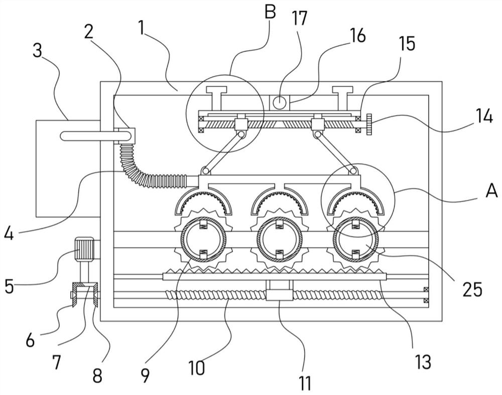
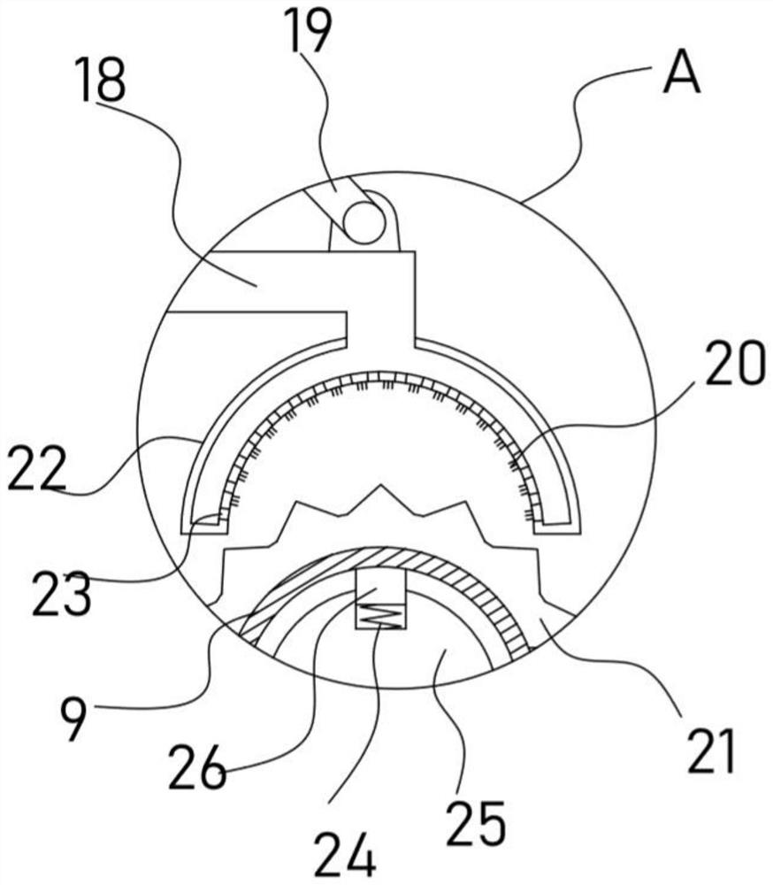
[0023] see Figure 1-4 , a steel pipe surface painting device for guardrail processing, comprising a fixed frame 1, a paint box 3 is fixed on the fixed frame 1, and several parallel rotating columns 25 are mounted on the fixed frame 1, and on the rotating column 25 A snap-fit ​​limit mechanism for fixing the steel pipe 9 is provided. The fixing frame 1 is provided with a conveying pipe 18 communicating with the paint tank 3. The conveying pipe 18 is connected with a paint brush vertically corresponding to the steel pipe 9. mechanism, the fixed frame 1 is driven with a sliding frame 15 through a longitudinal drive mechanism, and the sliding frame 15 is connected with the delivery pipe 18 through a lifting adjustment mechanism. The drive is connected with a transmission mechanism for driving the rotating column 25 to rotate.

[0024] When the device paints the surface of the steel pipe 9, it is limited by the clamping limit mechanism provided. Specifically, the clamping limit m...

Embodiment 2

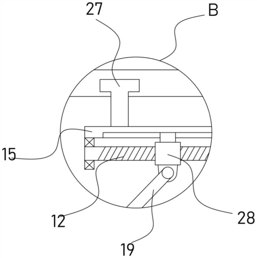
[0029] On the basis of Embodiment 1, in addition, the device is also provided with a longitudinal drive mechanism including a sliding frame 15, on which a longitudinal threaded block 16 is fixed, and the longitudinal threaded block 16 is internally threaded to be threaded with a longitudinal screw 17. A T-shaped slider 27 slidably embedded in the fixed frame 1 is fixed on the sliding frame 15 . The lifting adjustment mechanism includes two screw mandrels 12 that are coaxially fixed on the sliding frame 15 and are screwed in the opposite direction. The handwheels 14 are fixed on the screw mandrels 12, and the screw rods 12 are threaded with the sliding frame. 15 is slidably connected with a screw mandrel slider 28, and a suspender 19 is hinged between the screw mandrel slider 28 and the delivery pipe 18.

[0030] Through the above settings, turning the hand wheel 14 can drive the screw rod 12 to rotate, and the screw rod 12 drives the two screw rod sliders 28 to move toward or ...


PUM


Abstract

The invention discloses a steel pipe surface paint brushing device for protective fence machining and relates to the technical field of protective fence machining. The steel pipe surface paint brushing device comprises a fixed frame. Delivery pipes are connected with paint brushing mechanisms vertically corresponding to steel pipes. A sliding support is connected with the delivery pipes through alifting adjusting mechanism. A forward and reverse rotating mechanism is arranged on the fixed frame. The forward and reverse rotating mechanism is in driving connection with a driving mechanism usedfor driving rotary columns to rotate. The steel pipe surface paint brushing device can drive the driving mechanism through the forward and reverse rotating mechanism so that the driving mechanism candrive the steel pipes to rotate clockwise and counterclockwise alternately, and the paint brushing mechanisms can conduct circumferential uniform paint brushing on the surfaces of the steel pipes. Thesteel pipe surface paint brushing device is provided with a longitudinal driving mechanism which can drive the paint brushing mechanisms to move longitudinally to achieve the full and comprehensive paint brushing effect on different axial position regions on the steel pipes. The steel pipe surface paint brushing device is provided with a limiting mechanism capable of limiting on the steel pipes in the paint brushing process and can adapt to paint brushing operation of the steel pipes with different inner diameters.

Description

technical field [0001] The invention relates to the technical field of guardrail processing, in particular to a steel pipe surface painting device for guardrail processing. Background technique [0002] Fences are mainly used for protection and protection of equipment and facilities in factories, workshops and warehouses. It is usually made of steel, such as round steel pipe, square steel pipe or profiled steel plate. Surface treatment process: automatic electrostatic powder spraying or painting. The raw materials used for the surface treatment of outdoor crash barriers are waterproof materials. The anti-collision guardrail has a beautiful appearance and is not easy to rust. The columns of the anti-collision barrier are fixed to the ground through expansion bolts. It is usually installed on both sides of the logistics channel, around the production equipment, in the corner of the building, on both sides of the door and the edge of the cargo platform, etc. The protective...

Claims


Application Information

Patent Timeline
Patent Type & Authority Applications(China)
IPC IPC(8): B05B9/04B05B13/02B05B13/04B05B15/00B05B15/68
CPCB05B9/0403B05B13/0214B05B13/0228B05B13/0278B05B13/041B05B15/00B05B15/68
Inventor 芦海德
Owner 芦海德
Why Eureka
Try Eureka