Diaphragm rupture monitoring

A diaphragm and diaphragm pump technology, applied in pump testing, pump control, liquid variable capacity machinery, etc., can solve problems such as incompetence, large structure space, and complex technology.

Pending Publication Date: 2020-10-20
PROMINENT
View PDF0 Cites 1 Cited by
  • Summary
  • Abstract
  • Description
  • Claims
  • Application Information

AI Technical Summary

Problems solved by technology

[0009] This arrangement of the measuring chamber in the static area of ​​the diaphragm is technically complex and difficult, especially in the case of small dia

Method used


Image

  • Diaphragm rupture monitoring
  • Diaphragm rupture monitoring
  • Diaphragm rupture monitoring

Examples


Embodiment Construction

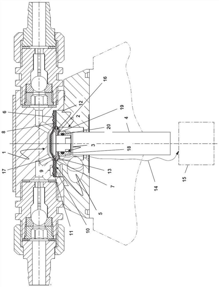
[0056] figure 1 is schematically showing the structure of the diaphragm unit 1 installed in the diaphragm pump.

[0057] The membrane unit 1 has a membrane core 2 which, in the exemplary embodiment shown, is constructed in two parts. The diaphragm core 2 has a threaded hole 3 as a receiving means for a push rod 4 . In the installed state of the diaphragm unit 1 , the diaphragm core 2 is connected to the drive of the diaphragm pump by means of a push rod 4 . According to the present application, the push rod 4 is not an integral part of the diaphragm unit, so that in the event of rupture or other failure of the diaphragm of the diaphragm unit, only the diaphragm unit 1 can be replaced without replacing the push rod 4 .

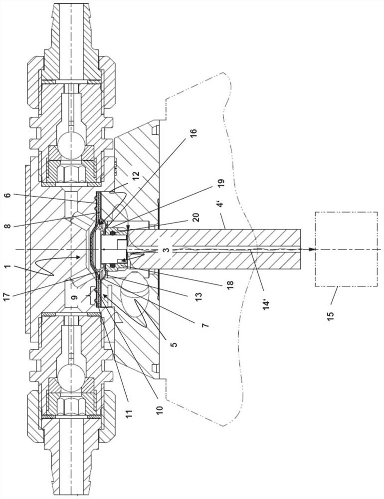
[0058] Also important for the diaphragm unit is the multilayer pump diaphragm 5 connected to the diaphragm core 2 .

[0059] exist Figure 1 to Figure 3 In the embodiment, the pump diaphragm 5 consists of three layers respectively. A fluid-tight working di...


PUM


Abstract

The present invention concerns a diaphragm unit for a diaphragm pump comprising a diaphragm core having a receiving means for a thrust rod of a pump drive, and a multi-layer pump diaphragm connected to the diaphragm core, wherein the pump diaphragm has a fluid-impermeable working diaphragm layer which in operation of the diaphragm pump comes into contact with a fluid to be delivered by the diaphragm pump, and a fluid-impermeable safety diaphragm layer, a sealed volume for receiving a fluid passing through the working diaphragm layer, that is arranged between the working diaphragm layer and thesafety diaphragm layer, and a first clamping region with which the pump diaphragm can be received in a receiving means of the diaphragm pump, wherein the first clamping region forms a ring which annularly surrounds the diaphragm core. To provide a diaphragm unit for a diaphragm pump which in a simple fashion permits detection of a rupture of the working diaphragm layer, according to the inventionit is proposed that provided within the ring formed by the first clamping region is at least one element of a sensor for detecting a fluid which penetrates into the sealed volume of the pump diaphragm.

Description

technical field [0001] The invention relates to a diaphragm unit for a diaphragm pump, comprising: a diaphragm core having a receiving device for a push rod of a pump drive; and a multilayer pump diaphragm, said multilayer pump diaphragm connected to a diaphragm core, wherein the pump diaphragm has: a fluid-tight working diaphragm layer in contact with the fluid to be delivered by the diaphragm pump during operation of the diaphragm pump; and a fluid-tight safety diaphragm layer a sealed volume for receiving fluid passing through the working diaphragm layer, said sealed volume being arranged between the working diaphragm layer and the safety diaphragm layer; and a first clamping region through which the pump diaphragm can be received In a receiving device for a diaphragm pump, wherein the first clamping area forms a ring annularly surrounding the diaphragm core, such that an annular area is provided between the first clamping area and the diaphragm core, said annular area is a...

Claims


Application Information

Patent Timeline
IPC IPC(8): F04B49/10F04B43/02
CPCF04B49/10F04B43/0081F04B43/02F04B43/009F04B51/00F04B43/0054
Inventor B·富雷斯勒A·巴波T·弗雷登伯格
Owner PROMINENT
Why Eureka
Try Eureka