
Photovoltaic structure for a new energy building

A building and new energy technology, applied in the support structure of photovoltaic modules, photovoltaic power generation, photovoltaic modules and other directions, can solve the problems of reducing the convenience of use, reducing the utilization rate of solar energy, and reducing the light absorption rate of photovoltaic panels, etc. The effect of improving reception and improving convenience

Active Publication Date: 2022-04-01
玖晔(广东)网络科技有限公司
View PDF15 Cites 1 Cited by
  • Summary
  • Abstract
  • Description
  • Claims
  • Application Information

AI Technical Summary

Problems solved by technology

[0003] Nowadays, the installation on the roof of the building is basically fixed on the roof of the building through a fixed bracket, and it is located to better absorb the light energy of the radiation. The photovoltaic panels are generally installed at an angle. With the passage of time every day, the sun rises from the east and gradually sets from the west, and the photovoltaic panel cannot change the angle at which the panel receives light according to the direction of the sun's rays, thereby reducing the absorption rate of the photovoltaic panel to light, and at the same time There are also some brackets that can manually or electrically adjust the inclination direction of the photovoltaic panel, so as to adjust according to the direction of the sun's rays. Manual adjustment often requires adjustment, which is cumbersome, time-consuming and laborious, and reduces the convenience of use. Electric adjustment requires The use of electricity causes the solar energy absorbed by the photovoltaic panel to be consumed, which reduces the utilization rate of solar energy. Therefore, it is necessary to design a photovoltaic structure that can eliminate the defects of manual or electric adjustment and at the same time better enable the photovoltaic panel to absorb solar energy.

Method used


Image

  • Photovoltaic structure for a new energy building
  • Photovoltaic structure for a new energy building
  • Photovoltaic structure for a new energy building

Examples


Embodiment Construction

[0031] The following will clearly and completely describe the technical solutions in the embodiments of the present invention with reference to the accompanying drawings in the embodiments of the present invention. Obviously, the described embodiments are only some, not all, embodiments of the present invention. Based on the embodiments of the present invention, all other embodiments obtained by persons of ordinary skill in the art without making creative efforts belong to the protection scope of the present invention.

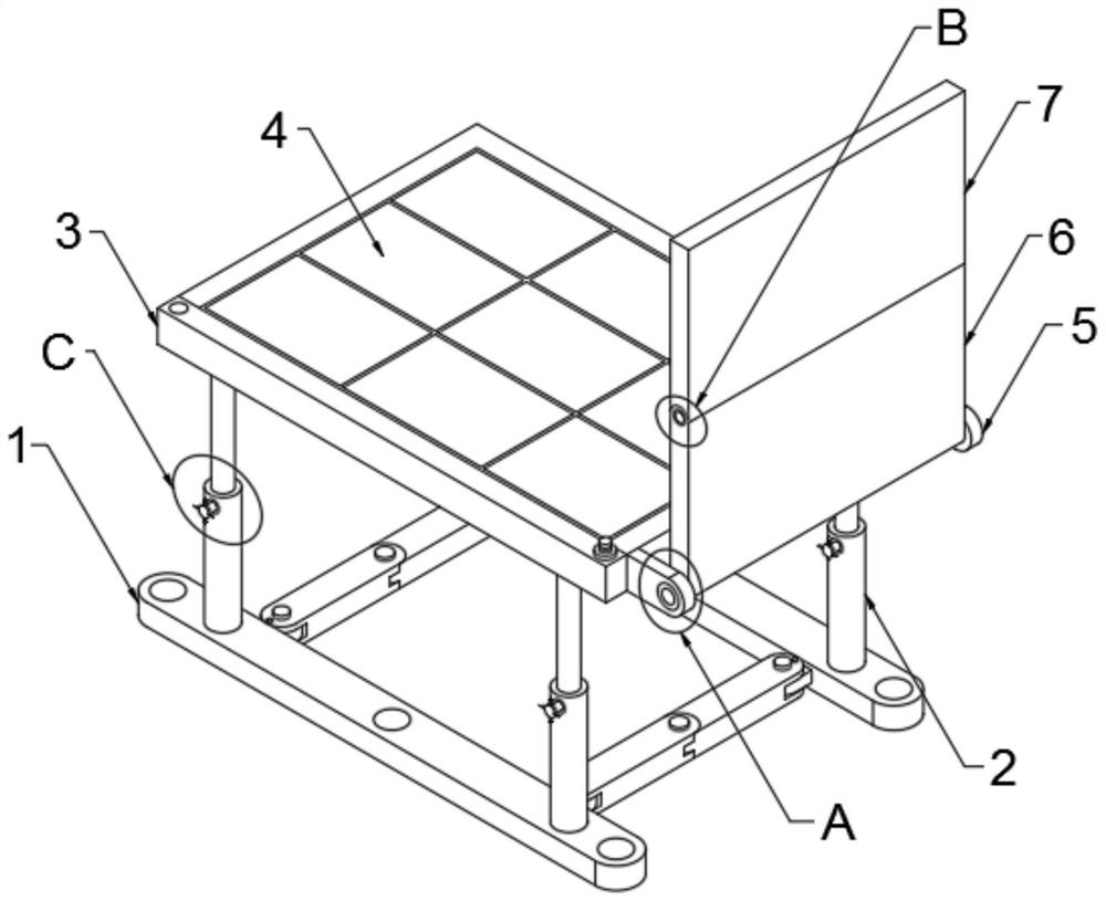
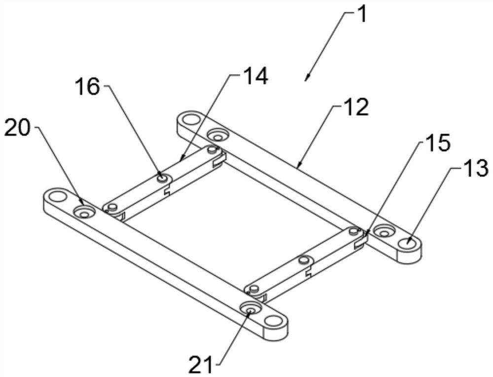
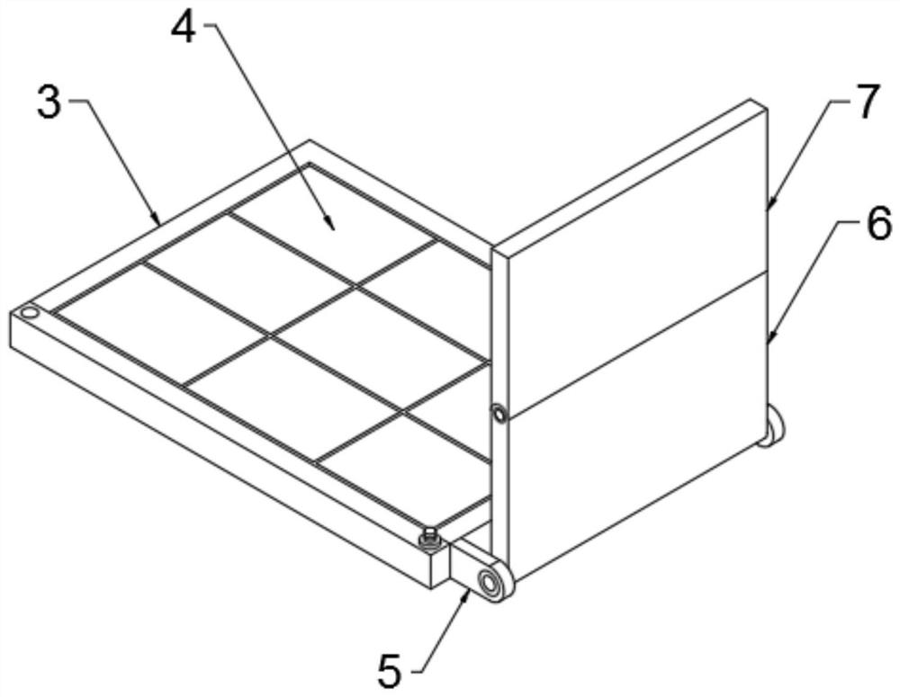
[0032] The present invention provides such Figure 1-10 A photovoltaic structure for a new energy building is shown, including a base 1, four support frames 2, a frame 3 and a plurality of photovoltaic panels 4, the frame 3 is fixedly connected to the base 1 through the support frame 2, and the plurality of photovoltaic panels 4 are fixed Set in the inner cavity of the frame 3, the base 1 includes two strip-shaped plates 12, and the tops of the two strip-shape...


PUM


Abstract

The invention discloses a photovoltaic structure for a new energy building, which includes a base, four support frames, a frame and a plurality of photovoltaic panels, one side of the frame is symmetrically fixedly connected with two fixing plates, and the two fixing plates are snapped together There is a first reflective panel, and a first rubber gasket is inserted between the first rotating pin and the fixed plate, the top of the first reflective panel is clamped with a second reflective panel, and the outer wall of the second rotating pin is fixedly sleeved with a second Rubber gasket. The present invention can manually adjust the first reflective panel and the second reflective panel by using the fixing plate, the first reflective panel, the second reflective panel, the first rotating pin, the second rotating pin, the first rubber washer and the second rubber washer provided on one side of the frame. The inclination angle of the two reflective panels makes the first reflective surface and the second reflective panel V-shaped, and when the sun’s rays are irradiated on the back of the photovoltaic panel, the sun’s rays can be refracted to the photovoltaic panel by using the principle of light refraction, thereby improving Reception of solar energy.

Description

technical field [0001] The invention relates to the field of new energy equipment, in particular to a photovoltaic structure for a new energy building. Background technique [0002] With the depletion of non-renewable energy sources and the deteriorating ecological environment, solar energy has become the key development and utilization direction of renewable energy in various countries due to its characteristics of safety, cleanness, abundant resources, and wide distribution. At present, in order to improve the practicality of new energy Efficiency requires that photovoltaic panels be installed on the roof of the building to absorb and utilize solar energy, thereby converting solar energy into electrical energy for use, thereby reducing the utilization rate of non-renewable energy and improving the protection of the ecological environment. [0003] Nowadays, the installation on the roof of the building is basically fixed on the roof of the building through a fixed bracket, ...

Claims


Application Information

Patent Timeline
Patent Type & Authority Patents(China)
IPC IPC(8): H02S20/30H02S30/20H02S40/22F24S30/20
CPCH02S20/30H02S30/20H02S40/22F24S30/20F24S2030/16Y02E10/52Y02B10/10Y02B10/20Y02E10/47
Inventor 向红英
Owner 玖晔(广东)网络科技有限公司
Learn More