A resin tile cold press shearing machine
A cutting machine and resin tile technology, applied in the field of resin tile cold press shearing machine, can solve the problems of cumbersome work, unattractive edges of resin tiles, fatigue, etc.
- Summary
- Abstract
- Description
- Claims
- Application Information
AI Technical Summary
Problems solved by technology
Method used
Image

Examples
Embodiment 1
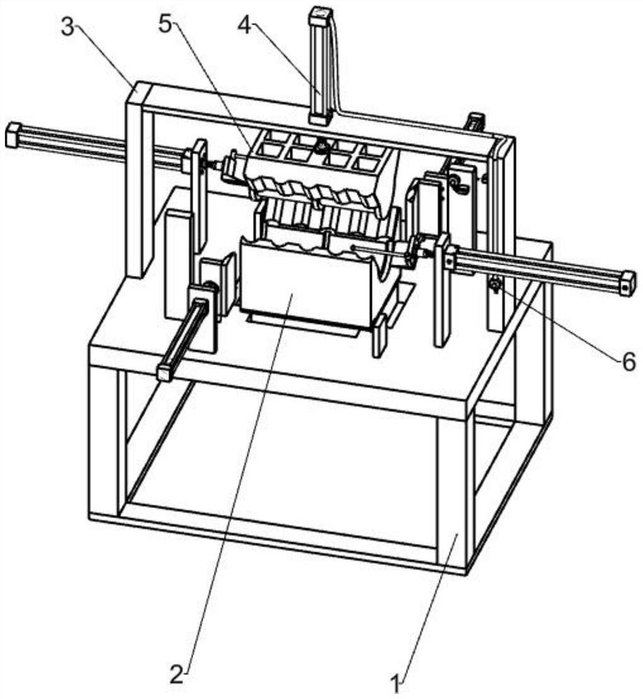
[0048] A resin tile cold press shearing machine, such as Figure 1-9 As shown, it includes a frame 1, a lower mold 2, a bracket 3, a first cylinder 4, an upper mold 5, a first switch 6 and a trimming device, the lower mold 2 is installed above the frame 1, and the bracket 3 is fixed on the machine. On the left and right sides above the frame 1, the first cylinder 4 is installed in the upper middle of the bracket 3, the upper mold 5 is installed on the telescopic rod of the first cylinder 4, the upper mold 5 is attached to the lower mold 2, and the first switch 6 is installed on the lower right end of the bracket 3 On the front side, the first switch 6 controls the first cylinder 4, and the trimming device is symmetrically installed above the frame 1.
[0049] When cold-pressing and cutting resin tiles, the resin tiles to be cut are manually placed on the lower mold 2, the first switch 6 is activated, the telescopic rod of the first cylinder 4 is stretched out, and the telescop...
Embodiment 2
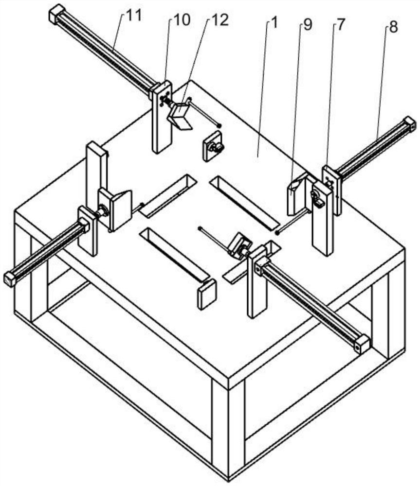
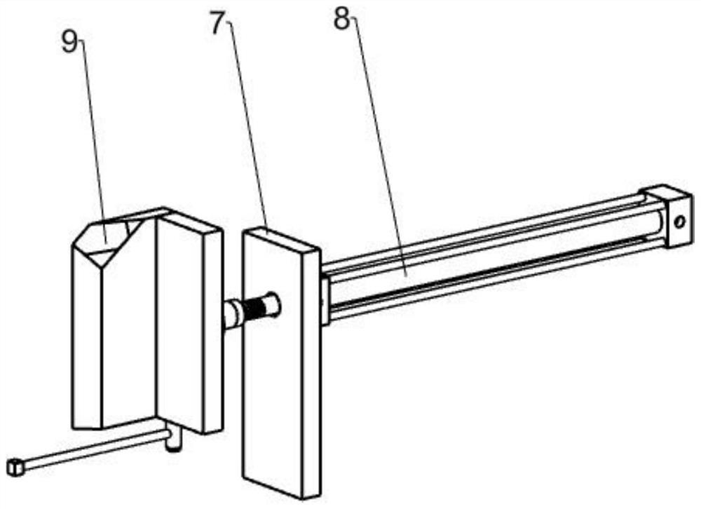
[0051] On the basis of Example 1, such as Figure 2-4 As shown, the trimming device includes a first mounting plate 7, a second cylinder 8, a straight cutter 9, a second mounting plate 10, a third cylinder 11 and a beveled cutter 12, and the two first mounting plates 7 are symmetrically fixed At the diagonal position above the frame 1, two second cylinders 8 are installed on one side of the first installation plate 7, two straight-face cutters 9 are installed on the telescopic rods of the second cylinder 8, and the two second installation plates 10 are fixed symmetrically At the diagonal position above the frame 1, two third air cylinders 11 are installed on one side of the second mounting plate 10, and there are two bevel cutters 12, which are respectively installed on the telescopic rods of the third air cylinders 11.
[0052] After the upper mold 5 and the lower mold 2 have cold-pressed the resin tile, start the expansion rod of the second cylinder 8 on the first mounting p...
Embodiment 3
[0054] On the basis of Example 2, such as Figure 5-9 As shown, a touch assembly is also included, and the touch assembly includes a push rod 13, a third mounting plate 14, a fourth mounting plate 141, a second switch 15, a rebound mechanism 16, a fifth mounting plate 17 and a sixth mounting plate 18, There are four push rods 13, and the push rods 13 are fixedly connected to the inclined-plane cutter 12 and the straight-face cutter 9 respectively. On the right side, a fourth mounting plate 141 is fixedly connected to the top of the frame 1, and the fourth mounting plate 141 is located on the left side of the second straight-face cutter 9. There are four second switches 15, and one of the second switches 15 is installed on the third mounting plate. On the front side of the plate 14, there are four rebounding mechanisms 16, wherein two rebounding mechanisms 16 are fixedly connected to the third mounting plate 14 and the fourth mounting plate 141 side, and the fifth mounting plat...
PUM
 Abstract
Description
Claims
Application Information