
Automatic feeding mechanism

A technology of automatic feeding and blocking mechanism, which is applied in the direction of conveyor objects, conveyor control devices, transportation and packaging, etc. It can solve the problems of inconvenient packaging or production, low efficiency, and automation equipment cannot be fully automated. Achieve the effect of improving production efficiency, high degree of automation, and neat feeding

Pending Publication Date: 2019-07-30
RULAMATE AUTOMATIC TECHN SUZHOU
View PDF0 Cites 5 Cited by
  • Summary
  • Abstract
  • Description
  • Claims
  • Application Information

AI Technical Summary

Problems solved by technology

[0002] The copper wire insulation used on the power steering motor is a rectangular yellow plastic part. Most of the product transportation of this yellow plastic part uses manual or automatic equipment. However, the existing automatic equipment cannot be fully automated and requires manual labor. Auxiliary work on the side is low in efficiency and inconvenient for later packaging or production. Therefore, we propose an automatic feeding mechanism

Method used


Image

  • Automatic feeding mechanism
  • Automatic feeding mechanism
  • Automatic feeding mechanism

Examples


Embodiment

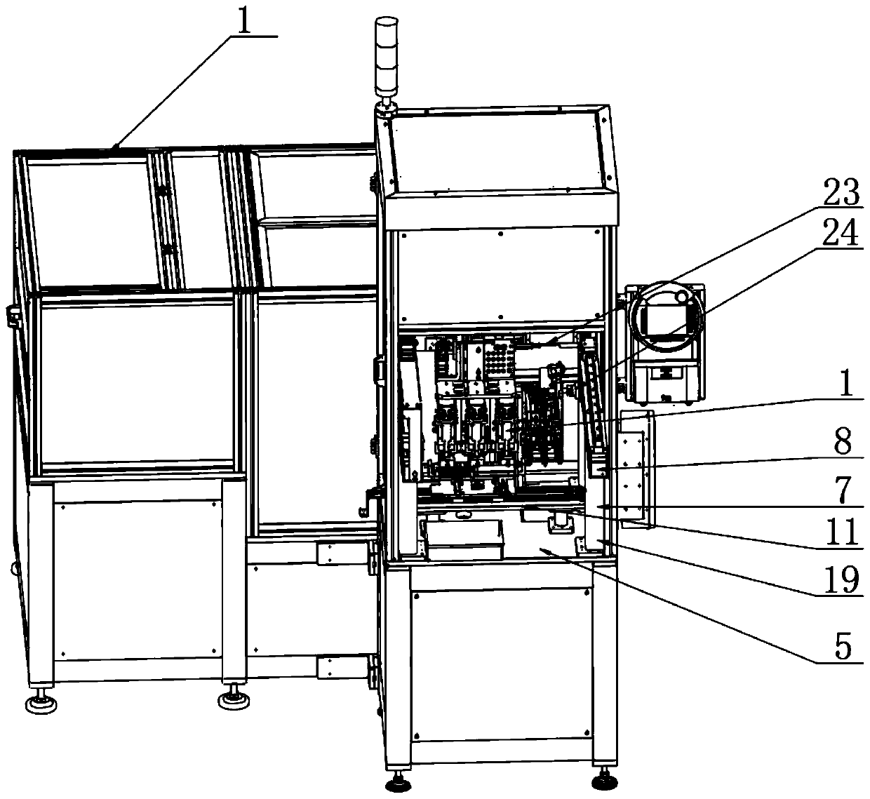
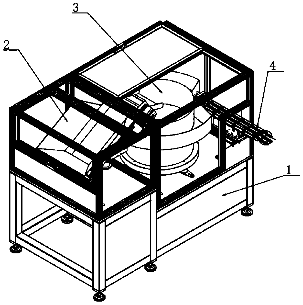
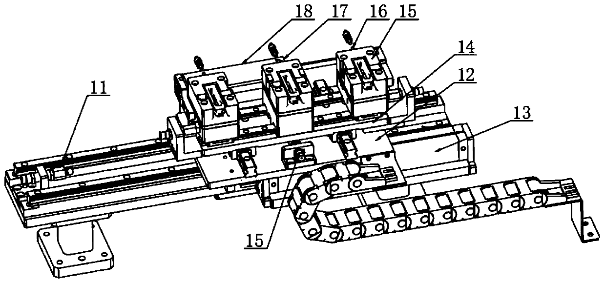
[0029] Embodiment: When in use, the product at the silo 2 enters the vibrating plate 3, and the vibrating plate 3 makes the products be transported through three groups of material channels 4 in an orderly manner (through the way of 1 out of 3), and the product is guided in the material channel 4 down into the tray 15, at this time, the driving cylinder 63 drives the receiving plate 64 to make the stoppers 65 enter the corresponding material channels 4 respectively, so that the product is blocked, and the in-position sensor 16 senses whether the product is on the tray 15. The material cylinder 17 drives the longitudinal sliding plate 14 to move forward, so that the tray 15 is separated from the material channel 4. When the tray 15 is separated from the material channel 4, the camera body 243 takes pictures, judges the front and back of the product and sends a PLC signal, and then the pallet separates the cylinder. 18. Separate the three groups of trays 15. After separation, the...


PUM


Abstract

The invention discloses an automatic feeding mechanism of the technical field of feeding mechanisms. The automatic feeding mechanism comprises a mounting rack I. The left side of the top of the mounting rack I is provided with a vibrating disk corresponding to the right end of a stock bin. Three material channels are arranged at a discharge port of the vibrating disk side by side. The outer wall of the front side of a push plate is uniformly provided with push protrusions matched with trays. The left side of the bottom of a mounting plate is movably connected with the output ends of electric cylinders. Clamping jaws are located in front of the push plate. The automatic feeding mechanism conducts automatic conveying through the three material channels in sequence. A stop mechanism is arranged and can stop products when the products are fed into the trays. The automatic feeding mechanism feeds the products into the trays comprehensively through a push cylinder, the push plate and the push protrusions. An up-down taking cylinder drives an L-shaped mounting plate to enable the clamping jaws to move downwards to clamp the products. The automatic feeding mechanism can convey the productsto mounting positions through the electric cylinders and horizontal movement cylinders II without manual operation. The automatic feeding mechanism is high in automation degree and tidy, stable and well-aligned in product feeding and facilitates later use.

Description

technical field [0001] The invention relates to the technical field of feeding mechanisms, in particular to an automatic feeding mechanism. Background technique [0002] The copper wire insulator used on the power steering motor is a rectangular yellow plastic part. Most of the product transportation of this yellow plastic part is carried by manual or automatic equipment. However, the existing automatic equipment cannot be fully automated and requires manual labor. Auxiliary work on the side is inefficient and inconvenient for later packaging or production. Therefore, we propose an automatic feeding mechanism. Contents of the invention [0003] The object of the present invention is to provide an automatic feeding mechanism to solve the problems raised in the above-mentioned background technology. [0004] In order to achieve the above object, the present invention provides the following technical solutions: an automatic feeding mechanism, including a mounting frame 1, th...

Claims


Application Information

Patent Timeline
Patent Type & Authority Applications(China)
IPC IPC(8): B65G43/08B65G47/82B65G47/90B65G47/14B65G47/88B65G47/244
CPCB65G43/08B65G47/82B65G47/902B65G47/1421B65G47/8815B65G47/244
Inventor 王江亿
Owner RULAMATE AUTOMATIC TECHN SUZHOU
Learn More