
Stent for blood flow improvement

a technology of stents and blood vessels, which is applied in the field of stents for blood vessels, can solve problems such as preventing the formation of aneurysms, and achieve the effects of preventing hyperplasia, preventing low shear stress flow, and preventing aneurysm formation

Inactive Publication Date: 2012-06-05
CARDIATIS SA
View PDF9 Cites 99 Cited by
  • Summary
  • Abstract
  • Description
  • Claims
  • Application Information

AI Technical Summary

Benefits of technology

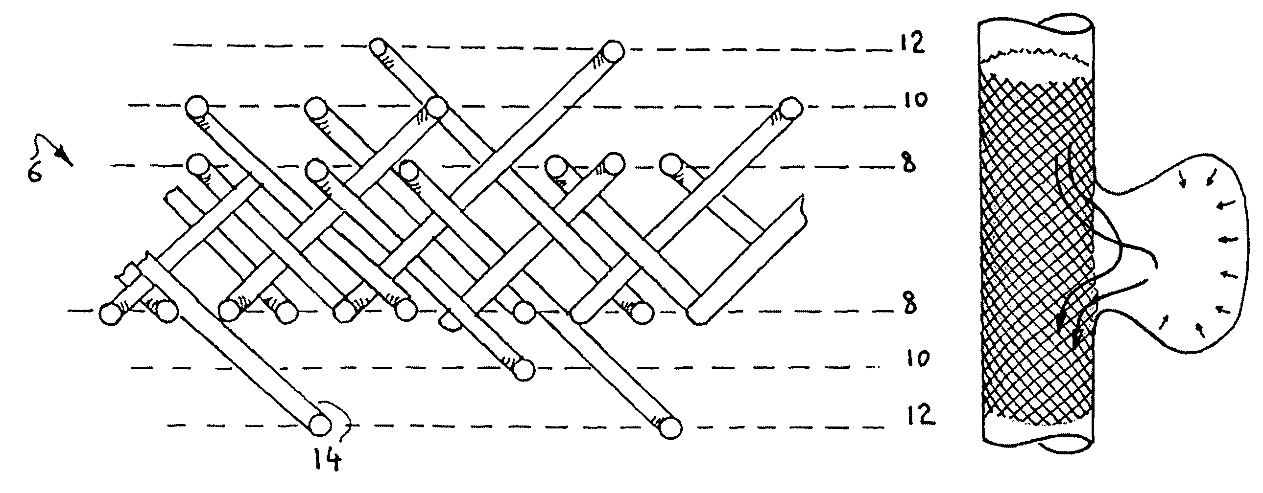
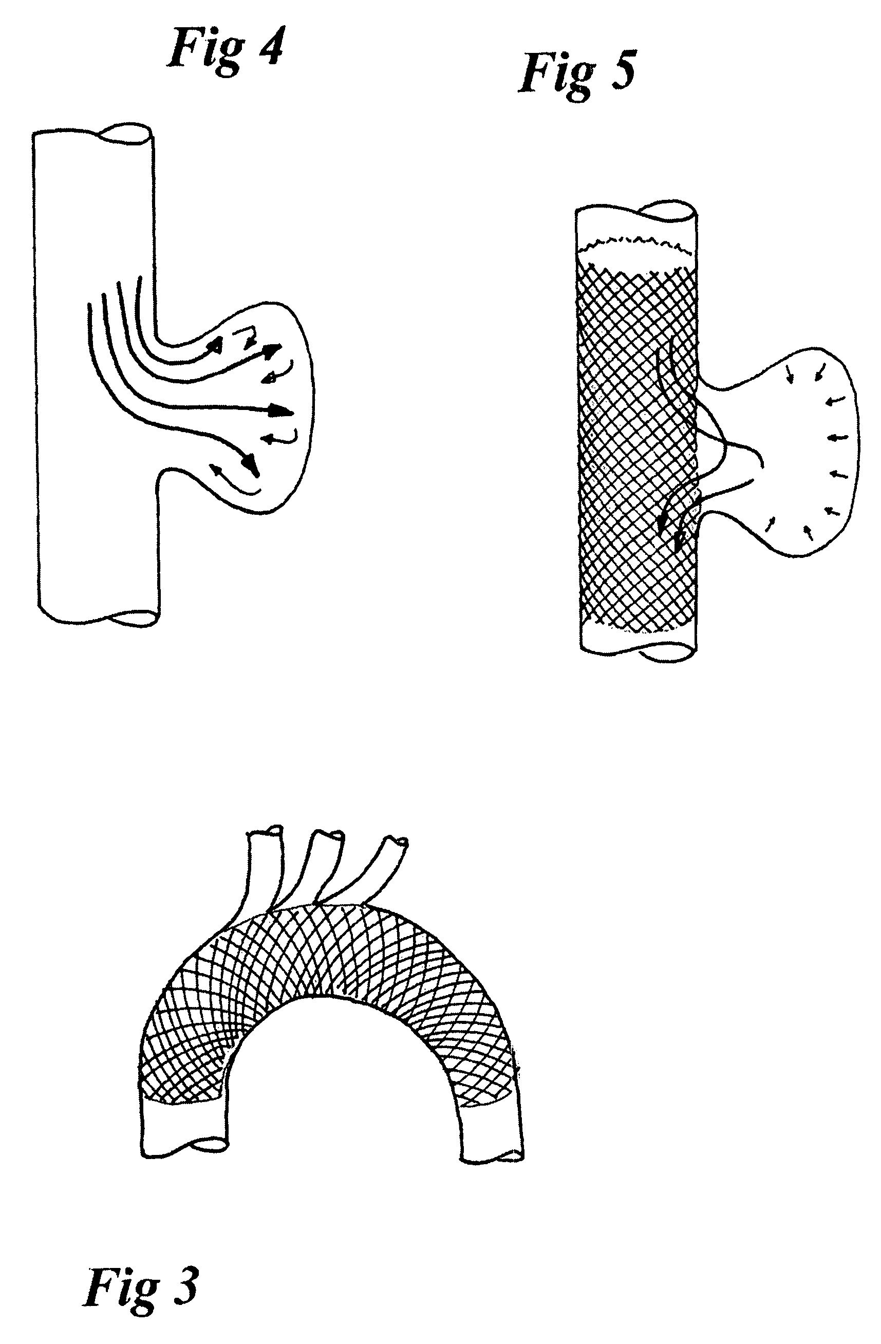
[0016]A main advantage of the present multi-layer framework is that it completely changes the haemodynamic properties of the side wall. Due to its particular porosity, it transforms the haemodynamic convection of the flow passing along it into a laminated diffusion flow passing through it, which reveals advantageous, particularly in the case of aneurysms. It also transforms the flow derivated towards a branch from turbulent to laminated, which impedes the forming of aneurysms. Finally, it avoids low shear stress flow along the wall of the covered vessel, preventing hyperplasia.
[0017]The multilayer stent has further physical and mechanical advantages over the other, single-layer, braided stents. It has the benefit of increased radial strength, a stability over a longer period of time, and better adaptation, due to the number of layers, to the type of artery and its pathology.
[0018]The structure preferably uses a single type of material, e.g. metal, ensuring its robustness and homogeneity.
[0021]The thickness of the wires can lie within the range of between 25 and 80 microns. The advantage of using thicker wires is that they afford a better hold against the wall of the vessels and allow the endoprosthesis to withstand, without damage, the various stresses to which the vessels are subjected, especially in the areas of the neck and the knee.
[0023]Conversely, in a prosthesis according to the invention, the mechanical properties of the wires of the different plies can be balanced in such a way as to perfectly compensate each other and ensure long-term stability.

Problems solved by technology

It also transforms the flow derivated towards a branch from turbulent to laminated, which impedes the forming of aneurysms.

Method used


Image

  • Stent for blood flow improvement
  • Stent for blood flow improvement
  • Stent for blood flow improvement

Examples


Embodiment Construction

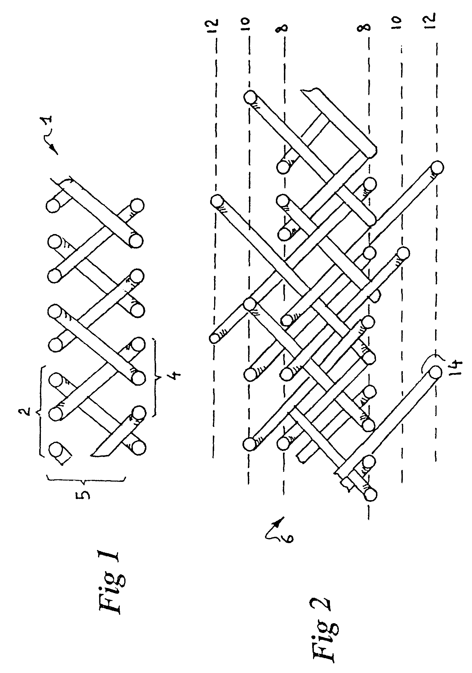
[0032]The traditional braided framework 1 is made up of a simple braid, two plies 2, 4 of wires, which are dextrogyratory 2 and laevogyratory 4, respectively, intersecting to form a simple braid 5.

[0033]The framework 6 of the invention is a multiple braid which comprises, in the example shown, three layers 8, 10, 12 whose plies are not distinct: at the time of braiding, a given number of wires 14 of the plies of the first layer 8 are interlaced with the plies of the second layer 10 and / or of the third layer 12, forming a complex lattice (this applies to the figure shown, but it goes without saying that the interlacing can continue to the Nth layer if the number of layers is N). The wires used for forming the braid being free of any heat treatment, they comply easily to the twisting and bending imposed by the braiding process. After braiding, the layers are stabilized by a heat treatment that freezes the relative position of the wires in each layer. This manner of proceeding opens up...


PUM

PropertyMeasurementUnit
thicknessaaaaaaaaaa
thicknessaaaaaaaaaa
thicknessaaaaaaaaaa

Abstract

Luminal endoprosthesis formed of a multi-layer braided framework. The framework is devoid of any cover layer, and formed of a plurality of stabilized layers of biocompatible metal wires which are interlaced, forming a lattice, a plurality of wires of a given layer being integrated in the lattice of the adjacent layers. The mechanical characteristics of an outermost layer is so that when in place, the layer applies against a vessel wall, the other layers extending substantially along cylindrical surfaces distinct from the outermost layer so as to form a multi-layer mat which affects the haemodynamic of a flow of blood passing along or through this mat and preventing a growing of plaque.

Description

CROSS-REFERENCE TO RELATED APPLICATION(S)[0001]The present application is a continuation-in-part of U.S. patent application Ser. No. 10 / 450,315 filed Nov. 21, 2003, now U.S. Pat. No. 7,588,597 B2, which is the National Stage of International Stage of International Application No. PCT / BE01 / 00210 filed Dec. 12, 2001.BACKGROUND OF THE INVENTION[0002]1. Field of the Invention[0003]The invention relates to luminal endoprostheses formed principally of a framework, without textile covering, generally called “stents”, and more particularly to stents for blood vessels, and i.a. for blood vessels bearing junctions.[0004]2. Description of the Related Art[0005]Over the years, the implantation of luminal endoprostheses has become an approved technique for treatment of aneurysms, atherosclerosis, etc.[0006]However, one crucial problem has still not been solved: namely that of perfectly matching the mechanical and hemodynamic characteristics of these endoprostheses and of the arteries in which the...

Claims


Application Information

Patent Timeline
Patent Type & Authority Patents(United States)
IPC IPC(8): A61F2/44A61F2/90
CPCA61F2/856A61F2/90A61F2002/0086Y10T29/49A61F2250/0036A61F2210/0076A61F2250/0023
Inventor FRID, NOUREDDINE
Owner CARDIATIS SA
Learn More