
Hanging device for computer screen

A suspension device and display technology, applied in the direction of supporting machines, mechanical equipment, etc., can solve the problems of troublesome disassembly and installation, limited application range of suspension devices, etc., and achieve the effect of convenient use, convenient installation and disassembly

Active Publication Date: 2022-02-08
WEIFANG ENG VOCATIONAL COLLEGE
View PDF6 Cites 0 Cited by
  • Summary
  • Abstract
  • Description
  • Claims
  • Application Information

AI Technical Summary

Problems solved by technology

[0003] China Invention Authorized Patent (Notice No.: CN106122733B) discloses a display screen suspension device, the suspension device includes a frame, a rotating assembly and a control assembly, the rotating assembly and the control assembly are respectively connected to the back of the frame; the frame can rotate around the rotating assembly , the inventor found that the technical solution has the following deficiencies in the actual use process: 1. Due to the different types of computer display screens, the interfaces with the suspension device are different, and different display screens have different interfaces, which leads to the suspension The scope of application of the device is limited; 2. Although the invention can rotate the display at a large angle to facilitate the disassembly of the suspension device, it still needs the cooperation of other users when rotating the display, or the display screen is supported. Still relatively troublesome during installation; 3, the existing elastic clamping suspension device is inconvenient to operate with both hands, and the two clamping arms need to be pulled apart on one side, and at the same time, the display screen will be inserted between the clamping arms. Therefore, it is often necessary to rely on two people to operate at the same time; 4. After the initial installation of the suspension device is completed, it is necessary to use an external verticality detection device for detection

Method used


Image

  • Hanging device for computer screen
  • Hanging device for computer screen
  • Hanging device for computer screen

Examples


Embodiment Construction

[0017] The technical solutions in the embodiments of the present invention will be clearly and completely described below in conjunction with the accompanying drawings in the embodiments of the present invention. Obviously, the described embodiments are only some of the embodiments of the present invention, not all of them. Based on the embodiments of the present invention, all other embodiments obtained by persons of ordinary skill in the art without creative work all belong to the protection scope of the present invention.

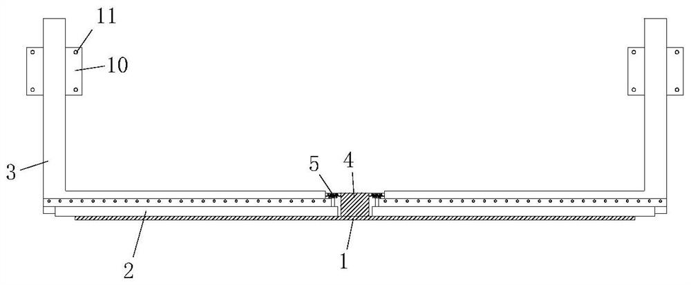
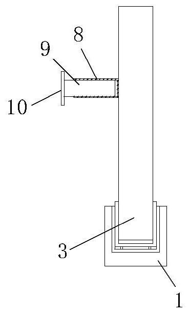
[0018] see Figure 1-3 , an embodiment provided by the present invention: a computer display screen suspension device, comprising a bottom groove 1, the two sides of the top of the bottom groove 1 are slidably connected with fixed rods 3 through two symmetrically arranged slide rails 2, so that The top of the bottom groove 1 is fixedly connected with a limit block 4, the limit block 4 is located on the same straight line as the central axis of the bottom...


PUM


Abstract

The invention discloses a computer display screen suspension device, which comprises a bottom groove, the two sides of the top of the bottom groove are slidably connected with fixing rods through two symmetrically arranged slide rails, and the top of the bottom groove is fixedly connected with a limit block . The present invention snaps together the edges of the computer display screen through two fixing rods, and the two fixing rods can adjust the position according to the size of the display screen, and can be applied to computer display screens with different installation structures, thereby solving the problems in the prior art. Due to different installation structures, the suspension device does not match the computer display screen; during installation and disassembly, the computer display screen can be detached from the suspension device and then installed and disassembled, which is convenient for users to install and disassemble. It solves the situation in the prior art that the display screen needs to be rotated to a certain angle when installing and dismounting the suspension device, and the installation and disassembly can only be performed, which facilitates the use of the user to a certain extent.

Description

technical field [0001] The invention relates to the technical field of computer accessories, in particular to a computer display screen suspension device. Background technique [0002] Displays are also often referred to as monitors. A monitor is an I / O device belonging to a computer, that is, an input and output device. It is a display tool that displays certain electronic files on the screen through a specific transmission device and then reflects them to the human eye. [0003] China Invention Authorized Patent (Notice No.: CN106122733B) discloses a display screen suspension device, the suspension device includes a frame, a rotating assembly and a control assembly, the rotating assembly and the control assembly are respectively connected to the back of the frame; the frame can rotate around the rotating assembly , the inventor found that the technical solution has the following deficiencies in the actual use process: 1. Due to the different types of computer display scre...

Claims


Application Information

Patent Timeline
Patent Type & Authority Patents(China)
IPC IPC(8): F16M13/02
CPCF16M13/02
Inventor 常祖政褚海燕
Owner WEIFANG ENG VOCATIONAL COLLEGE
Learn More