Shot blasting clamp for thin-wall frame part

A technology for frames and parts, applied in the field of shot peening fixtures for thin-walled frame parts, to achieve the effect of improving processing efficiency, improving efficiency, and simple flip feeding operation

Pending Publication Date: 2021-10-15
湖南应用技术学院
View PDF11 Cites 0 Cited by
  • Summary
  • Abstract
  • Description
  • Claims
  • Application Information

AI Technical Summary

Problems solved by technology

[0004] In view of this, the object of the present invention is to provide a thin-walled frame parts shot peening fixture, to at least partially solve the problem of controlling the shot peening distance, shot peening angle and other parameters in a more suitable range during shot peening of thin-walled frame parts. , to improve the effect of shot peening

Method used


Image

  • Shot blasting clamp for thin-wall frame part
  • Shot blasting clamp for thin-wall frame part
  • Shot blasting clamp for thin-wall frame part

Examples


Embodiment Construction

[0033] The following will clearly and completely describe the technical solutions in the embodiments of the present invention with reference to the accompanying drawings in the embodiments of the present invention. Obviously, the described embodiments are only some, not all, embodiments of the present invention. The components of the embodiments of the invention generally described and illustrated in the figures herein may be arranged and designed in a variety of different configurations. Accordingly, the following detailed description of the embodiments of the invention provided in the accompanying drawings is not intended to limit the scope of the claimed invention, but merely represents selected embodiments of the invention. Based on the embodiments of the present invention, all other embodiments obtained by those skilled in the art without making creative efforts belong to the protection scope of the present invention.

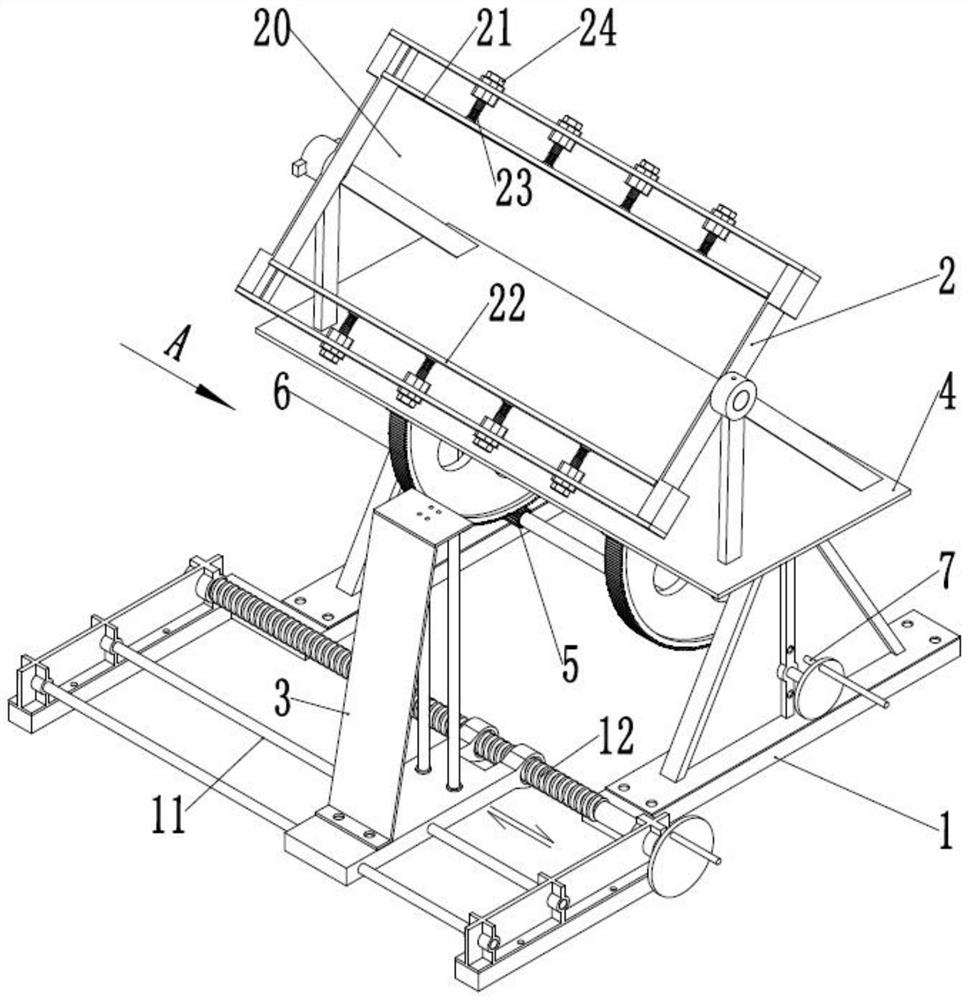
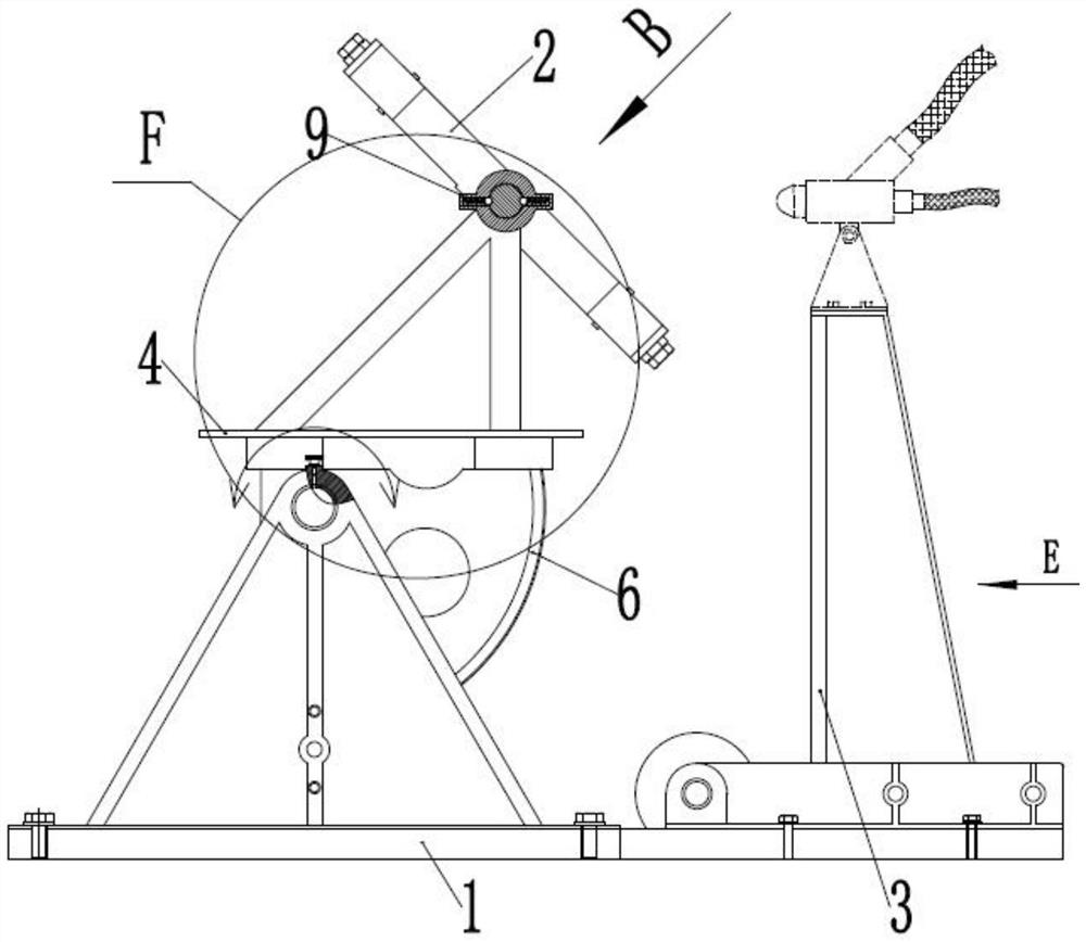
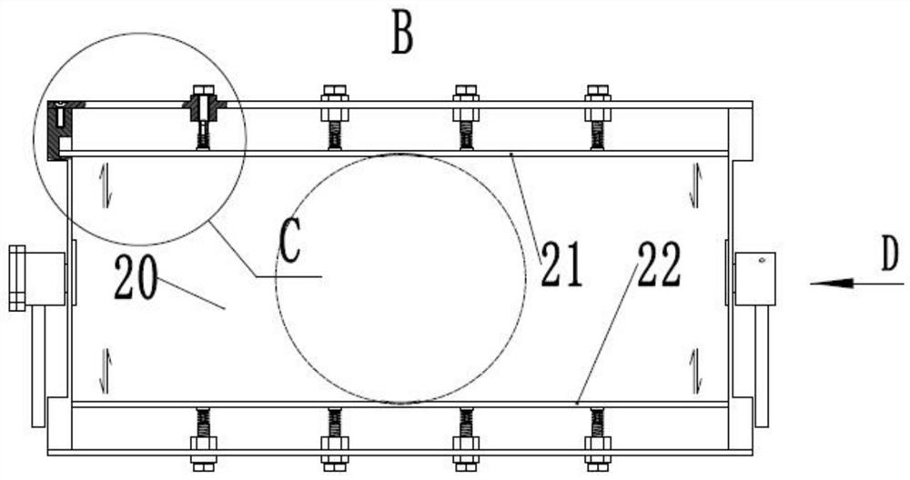
[0034] see Figure 1-Figure 8 , the embodiment of t...


PUM


Abstract

The invention discloses a shot blasting clamp for a thin-wall frame part, and relates to the technical field of shot blasting processing equipment. The shot blasting clamp comprises a rack, a clamp body and a spray head mounting frame, wherein the two sides of the clamp body are rotatably mounted on the rack, and are driven by a turnover mechanism; a clamping cavity is formed in the clamp body; a first clamping plate and a second clamping plate are symmetrically arranged in the clamping cavity; the first clamping plate and the second clamping plate are separately mounted on the clamp body through telescopic mechanisms to realize relative movement of the first clamping plate and the second clamping plate; the spray head mounting frame is movably arranged on the rack through a linear reciprocating feeding mechanism, and the moving direction of the spray head mounting frame is parallel to the rotary axis of the clamp body; and a spray head with a spray hole aligned to the clamping cavity is further mounted on the spray head mounting frame. According to the shot blasting clamp for the thin-wall frame part disclosed by the invention, parameters such as shot blasting distance and shot blasting angle can be controlled within a relatively proper range during shot blasting of the thin-wall frame part, so that shot blasting strengthening effect is improved.

Description

technical field [0001] The invention relates to the technical field of shot peening processing equipment, in particular to a shot peening fixture for thin-walled frame parts. Background technique [0002] With the extensive use of thin-walled frame parts in aerospace equipment, higher requirements have to be put forward for the fatigue resistance and stability of thin-walled frame parts. Shot peening is usually used to improve the performance of parts. For thin-walled frame parts, it is difficult to comprehensively and uniformly shot peen them because of their complexity and diversity. [0003] However, parameters such as shot peening angle, shot peening time and shot peening distance have a crucial impact on the effect of shot peening. The traditional method of manually moving the nozzle to peen parts cannot control these shot peening parameters well. . It is a technical problem to be solved urgently to shot peen the thin-walled frame parts uniformly at different angles. ...

Claims


Application Information

Patent Timeline
Patent Type & Authority Applications(China)
IPC IPC(8): B24C9/00B24C1/10
CPCB24C9/00B24C1/10
Inventor 蒋双庆李娅李洋邓茂盛廖凯
Owner 湖南应用技术学院
Why Eureka
Try Eureka