Pneumatic numerical control shot blasting machine

A shot peening machine, pneumatic technology, applied in abrasive jet machine tools, used abrasive treatment devices, abrasives, etc. Processing speed and other issues to achieve the effect of improving the efficiency and quality of shot peening, improving the quality of shot peening, and reducing fragmentation and fracture

Inactive Publication Date: 2020-11-06
芜湖辉悦机械设计有限公司
View PDF0 Cites 0 Cited by
  • Summary
  • Abstract
  • Description
  • Claims
  • Application Information

AI Technical Summary

Problems solved by technology

[0003] When the workpiece is shot peened, the traditional shot peening device often cannot process the workpiece synchronously, although there are many kinds of shot peening equipment, for example, in a drum type shot peening equipment, the workpiece is placed on the drum of the equipment , and a nozzle is set to spray the shot blasting material onto the workpiece through an opening in the drum, and at the same time, the workpiece is shot blasted by rotating the drum to agitate the workpiece, but this equipment can only process the workpiece through the opening of the drum, As a result, the speed of workpiece shot peening is greatly affected, and this rotary drum type shot peening equipment needs to quickly stir the workpiece to prevent the workpiece from falling from the opening, causing the workpiece to be broken and broken during frequent collisions, which in turn affects the shot peening of the workpiece. quality of processing
[0004] Although the pneumatic CNC shot blasting machine in the prior art can process multiple workpieces through the screen-type tube, due to the accumulation of multiple workpieces inside the tube, there are still collisions between the internal workpieces when the tube rotates phenomenon, so that the workpiece is prone to breakage and fracture in frequent collisions, which affects the quality of the shot peening treatment of the workpiece

Method used


Image

  • Pneumatic numerical control shot blasting machine
  • Pneumatic numerical control shot blasting machine
  • Pneumatic numerical control shot blasting machine

Examples


Embodiment approach

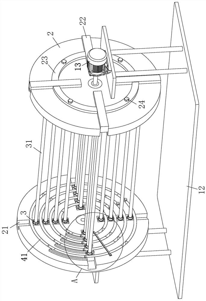
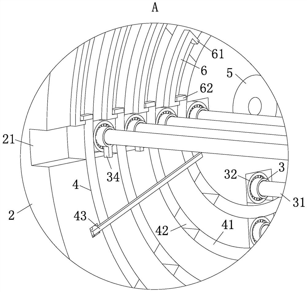
[0025] As an embodiment of the present invention, a group of annular grooves 4 are respectively provided on the end faces of the turntable 2 close to each other, and annular plates 41 with matching shapes are respectively connected to the inner portions of the annular grooves 4 . The outer end faces of 41 are respectively provided with communicating grooves 42 that can cooperate with the slots 21. During work, in order to make the workpiece 31 pre-installed between the two rotating disks 2 more conveniently and quickly, at this time, by setting the annular grooves 4 that cooperate with each other With the annular plate 41, when the workpiece 31 is inserted into the slot 21 between the two symmetrical turntables 2, the connecting grooves 42 on the end surface of the annular plate 41 are aligned with the slots 21 respectively through the rotation of the annular plate 41 inside the annular groove 4. When the workpiece 31 can slide through the connecting groove 42 in the slot 21, a...


PUM


Abstract

The invention belongs to the technical field of shot blasting, and particularly relates to a pneumatic numerical control shot blasting machine. The pneumatic numerical control shot blasting machine comprises a box body and spray heads. A fixing frame is arranged in the box body, rotary discs are symmetrically installed at the two ends of the fixing frame, and a set of inserting grooves are formedin the end faces of the rotary discs. Fixing rings are slidably connected into the inserting grooves. The inserting grooves in one rotating disc is set as through grooves and are internally connectedwith fastening plates, wherein every two adjacent fastening plates are connected through a connecting plate, the side wall of each connecting plate is in threaded connection with the rotating disc through a fastening bolt, a motor is installed at the outer end of the rotating disc, and the end of the motor is connected with the middle of the rotating disc through a rotating shaft. According to theshot blasting machine, workpieces are uniformly arranged and fixed between the two rotary discs, the situation that the workpieces shade one another during stacking treatment can be effectively reduced, and the breakage and fracture of the workpieces caused by mutual collision can also be reduced, so that the shot blasting treatment efficiency and quality of the workpieces are greatly improved.

Description

technical field [0001] The invention belongs to the technical field of shot blasting, in particular to a pneumatic numerical control shot blasting machine. Background technique [0002] Shot blasting equipment is generally used for surface treatment of, for example, a rare earth metal-based permanent magnet, that is, a treatment for removing an oxide layer formed on the surface, or for shot blasting treatment for finely treating a film formed on the surface. [0003] When the workpiece is shot peened, the traditional shot peening device often cannot process the workpiece synchronously, although there are many kinds of shot peening equipment, for example, in a drum type shot peening equipment, the workpiece is placed on the drum of the equipment , and a nozzle is set to spray the shot blasting material onto the workpiece through an opening in the drum, and at the same time, the workpiece is shot blasted by rotating the drum to agitate the workpiece, but this equipment can onl...

Claims


Application Information

Patent Timeline
Patent Type & Authority Applications(China)
IPC IPC(8): B24C1/08B24C3/24B24C9/00
CPCB24C1/08B24C3/24B24C9/00
Inventor 程慧玲陆玉琴
Owner 芜湖辉悦机械设计有限公司
Why Eureka
Try Eureka