Knob

A technology of knobs and substrates, applied in the field of knobs, can solve problems such as the complexity of the combination of touch sensing functions and knobs

Active Publication Date: 2020-10-30
TIANMA MICRO ELECTRONICS
11 Cites 1 Cited by

AI-Extracted Technical Summary

Problems solved by technology

In the prior art, in order to combine the touch sensing function with the knob, the knob needs to be arranged on the touch display panel to utili...

Method used

[0030] According to the knob 100 of the embodiment of the present invention, the substrate 120 is disposed at one end of the fixed column 110, and the substrate 120 is provided with a first touch sensing device including a plurality of capacitors. When the finger touches the conductive housing 140 of the knob 100, the conductive housing 140 communicates with the finger. The conductive housing 140 includes a conductive portion 141 spaced apart from a plurality of touch electrodes 131, wherein the conductive portion 141 is connected to the substrate 120. Coupled with one of the capacitors on the conductive shell 140 and the conduction part 141, it is equivalent to coupling a finger with one of the capacitors, thereby changing the capacitance of the capacitor, so that the first touch sensing component 130 and the knob 100 can generate a corresponding touch information. When turning the knob 100, through the conduction of the conductive housing 140 and the conductive part 141, the finger is indirectly coupled with one of the plurality of capacitors selectively, that is, the finger is indirectly coupled with a capacitor, and by rotating the knob 100, the finger can be coupled with the capacitor. The coupling capacitor is changed, so that the controller 180 can receive different touch information according to the rotation of the knob 100, realize the identification of the touch position, and be convenient to be applied to the adjustment of functions and gear positions. The embodiment of the present invention has a touch-sensing component itself, integrates the touch-sensing function into the knob with a more streamlined structure, and no longer relies on the touch-sensing function of the external touch display panel, so that it is more convenient to be independently applied to various in the display panel device.
[0035] The knob 100 can be configured to have a plurality of gear positions, wherein a plurality of capacitors are set in one-to-one correspondence with the plurality of gear positions. For example, if the multiple touch electrodes 131 of the first touch sensing component 130 are configured to have 10 capacitors, then the knob 100 may be configured to have 10 gears, and each gear corresponds to a corresponding capacitor. In some embodiments, the orthographic projection of the conductive part 141 on the substrate 120 can cover the orthographic projection of the touch electrode 131 corresponding to a capacitor on the substrate 120, so that the conductive part 141 can correspond to a touch electrode corresponding to each gear. 131 is fully coupled to ensure accurate identification of capacitance change information by the first touch sensing component 130 and improve the sensitivity of rotation sensing.
[0037] Please continue to refer to FIG. 2 , in some embodiments, at least part of the touch electrodes 131 are attached to the second surface S2 of the substrate 120 . Wherein, the distance D1 between the conductive part 141 and the touch electrode 131 attached to the second surface S2 of the substrate 120 in the direction perpendicular to the substrate 120 is 0.5 mm to 5 mm, so as to ensure the coupling between the conductive part 141 and the touch electrode 131. Stability, to avoid poor induction caused by too large a distance. In one example, a distance D1 between the conductive portion 141 and the touch electrodes 131 attached to the second surface S2 of the substrate 120 in a direction perpendicular to the substrate 120 is 1 mm.
[0044] The number of the first driving electrode TX1 is not limited to one. FIG. 8 is a schematic top view of a knob provided acco...

Abstract

The invention discloses a knob, which comprises a fixing column, a substrate, a first touch sensing assembly, a conductive shell and a controller, wherein the substrate has a central region at the center of the substrate and an edge region disposed around the central region, the first touch sensing assembly is arranged in the edge region of the substrate, a first touch sensing device comprises a plurality of touch electrodes, the touch electrodes are configured to be provided with a plurality of capacitors, the conductive shell sleeves the peripheral side of the fixing column, the conductive shell comprises conduction parts arranged at intervals with the plurality of touch electrodes, and can rotate around a shaft parallel to the axial direction of the fixing column relative to the fixingcolumn so as to selectively couple the conduction part with one of the plurality of capacitors, the first touch sensing assembly is electrically connected with the controller, and the controller can receive touch information generated by coupling of the conduction part and the capacitor. The embodiment of the invention is provided with the touch sensing assembly, so that the touch sensing functionis integrated in the knob by a simple structure.

Application Domain

Controlling membersElectronic switching +1

Technology Topic

PhysicsElectrically conductive +9

Image

  • Knob
  • Knob
  • Knob

Examples

  • Experimental program(1)

Example Embodiment

[0021] The features and exemplary embodiments of various aspects of the present invention will be described in detail below. In order to make the objectives, technical solutions and advantages of the present invention more clear, the present invention will be further described in detail below with reference to the accompanying drawings and specific embodiments. It should be understood that the specific embodiments described herein are only configured to explain the present invention, and are not configured to limit the present invention. It will be apparent to those skilled in the art that the present invention may be practiced without some of these specific details. The following description of the embodiments is only intended to provide a better understanding of the present invention by illustrating examples of the invention.
[0022] It should be noted that, in this document, relational terms such as first and second are only used to distinguish one entity or operation from another entity or operation, and do not necessarily require or imply any relationship between these entities or operations. any such actual relationship or sequence exists.
[0023] It will be understood that, in describing the structure of a component, when a layer or region is referred to as being "on" or "over" another layer or region, it can be directly on the other layer or region, or Other layers or regions are also included between it and another layer, another region. And, if the part is turned over, that layer, one area, will be "below" or "beneath" another layer, another area.
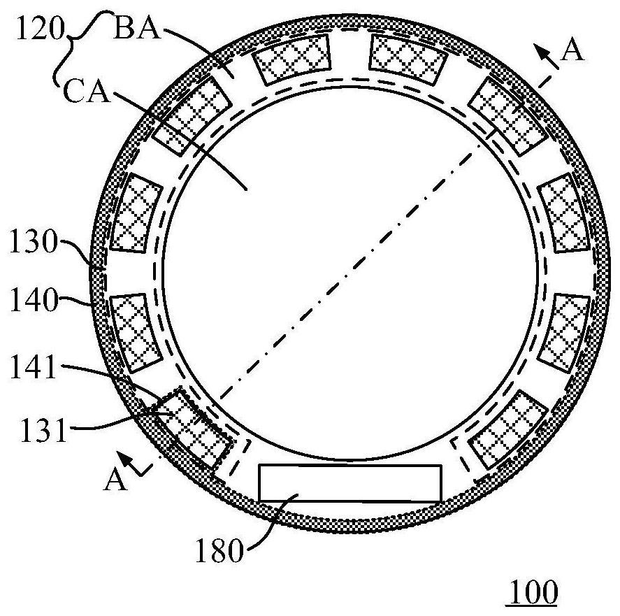
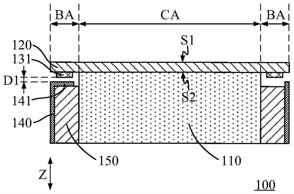
[0024] figure 1 , figure 2 are a schematic top view and a schematic cross-sectional view of a knob provided according to an embodiment of the present invention, wherein figure 1 The A-A line in the shown figure 2 The interception position of the cross-sectional schematic diagram. The knob 100 includes a fixing column 110 , a substrate 120 , a first touch sensing component 130 , a conductive housing 140 and a controller 180 . The controller 180 may be a driver chip, or a flexible printed circuit (Flexible Printed Circuit, FPC) with a touch sensing driving function.
[0025] The fixing column 110 may be a cylindrical or hollow cylindrical structure, wherein the fixing column 110 is an insulating member. In some embodiments, the substrate 120 is a circuit board, such as an FPC, in which case the controller 180 may be a driver chip integrated on the substrate 120 . In some embodiments, the substrate 120 is an insulating plate, and the controller 180 may be an FPC bound and connected to a predetermined area of ​​the substrate 120 . In some embodiments, the substrate 120 may be made of a light-transmitting material, such as glass, polyimide (PI), or the like.
[0026] The base plate 120 is arranged at one end of the fixing column 110 along the axis Z of the fixing column 110 . For example, in this embodiment, the base plate 120 is arranged at the top end of the fixing column. The substrate 120 includes a first surface S1 facing away from the fixing post 110 and a second surface S2 facing the fixing post 110 , wherein the substrate 120 has a center area CA at its center and an edge area BA disposed around the center area CA. In this embodiment, the substrate 120 has a substantially circular structure, the central area CA is a circular area, and the edge area BA is an annular area.
[0027] The first touch sensing element 130 is disposed in the edge area BA of the substrate 120 . The first touch sensing device may include a plurality of touch electrodes 131 attached to the substrate 120 , the plurality of touch electrodes 131 are arranged around the central area CA, and the plurality of touch electrodes 131 are configured to have a plurality of capacitors. In some embodiments, the plurality of touch electrodes 131 are disposed around the entire periphery of the central area CA, and in other embodiments, the plurality of touch electrodes 131 are disposed around a part of the periphery of the central area CA, that is, are disposed half around the central area CA .
[0028] The conductive shell 140 is sleeved on the outer peripheral side of the fixing column 110 and is located on the side where the second surface S2 of the substrate 120 is located. The conductive housing 140 includes a conductive portion 141 spaced from the plurality of touch electrodes 131 , and the conductive portion 141 is a conductive structure. In some embodiments, the conductive portion 141 has a sheet-like structure parallel to the substrate 100 . The conductive housing 140 can rotate relative to the fixing column 110 around an axis parallel to the axis Z of the fixing column 110 , so that the conductive portion 141 is selectively coupled with one of the plurality of capacitors. That is, the conductive portion 141 is coupled to one capacitor, and by rotating, the capacitor coupled to the conductive portion can be changed to the next capacitor.
[0029] In this embodiment, the controller 180 may be a driver chip, the controller 180 may be disposed on the edge area BA of the substrate 120 , the first touch sensing component 130 is electrically connected to the controller 180 , and the controller 180 can receive the conductive portion 141 and couple with the capacitor generated touch information. In some embodiments, each touch electrode 131 is electrically connected to the controller 180 through a touch signal line.
[0030] According to the knob 100 of the embodiment of the present invention, the substrate 120 is disposed at one end of the fixing column 110 , and the first touch sensing device including a plurality of capacitors is disposed on the substrate 120 . When a finger touches the conductive housing 140 of the knob 100 , the conductive housing 140 communicates with the finger. The conductive housing 140 includes a conductive portion 141 spaced from the plurality of touch electrodes 131 , wherein the conductive portion 141 is connected to the substrate 120 . Coupling with one of the capacitors on the touch panel, through the conduction of the conductive housing 140 and the conductive portion 141, is equivalent to coupling a finger with one of the capacitors, thereby changing the capacitance of the capacitor, so that the first touch sensing component 130 and the knob 100 can generate corresponding touches information. When the knob 100 is rotated, the conductive shell 140 and the conduction portion 141 conduct conduction, so that the finger is indirectly coupled with one of the plurality of capacitors, that is, the finger is indirectly coupled with one capacitor, and by rotating the knob 100, the finger can be selectively coupled with the finger The coupled capacitors are changed, so that the controller 180 can receive different touch information according to the rotation of the knob 100 , realize the recognition of the touch position, and facilitate application in the adjustment of functions and gears. The embodiment of the present invention has its own touch-sensing component, integrates the touch-sensing function into the knob with a more streamlined structure, and no longer relies on the touch-sensing function of the external touch display panel, so that it is more convenient to be independently applied to a variety of non-touch display panel device.
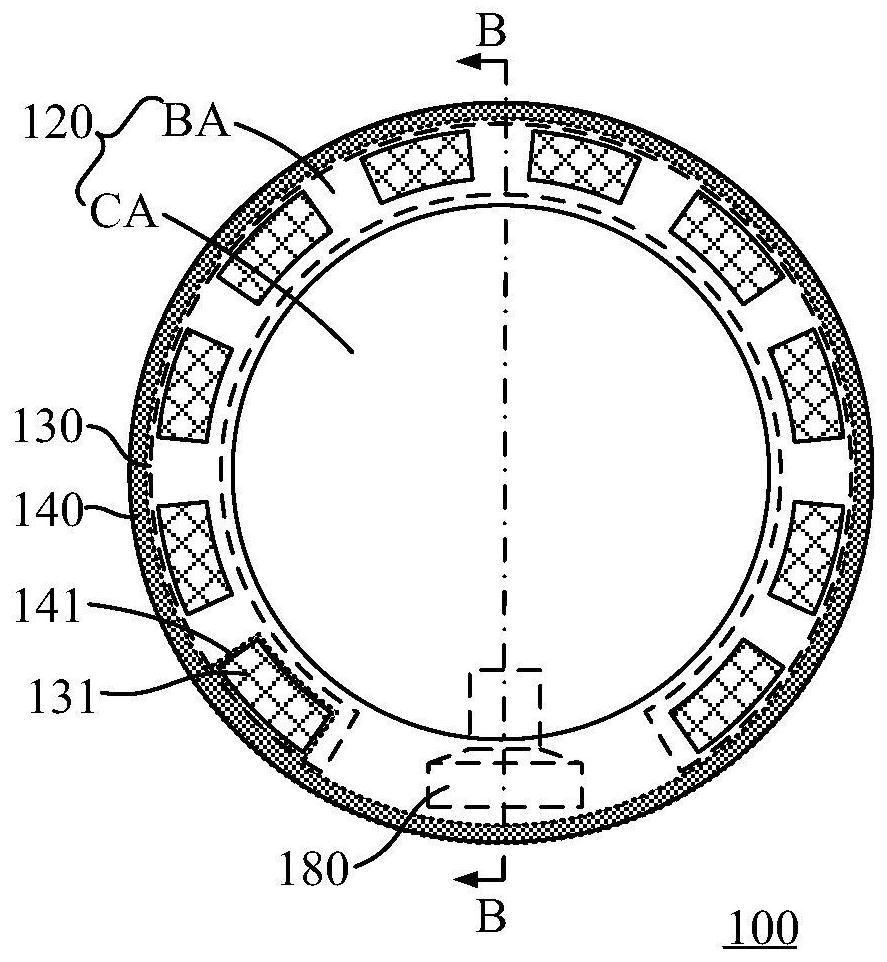
[0031] image 3 , Figure 4 are a schematic top view and a schematic cross-sectional view of a knob provided according to another embodiment of the present invention, wherein image 3 The B-B line in the Figure 4The interception position of the cross-sectional schematic diagram. In some embodiments, the controller 180 may be an FPC bound and connected to a preset area of ​​the substrate 120 , and the FPC may have a touch-sensing driving function. For example, the substrate 120 includes a binding area disposed in the edge area BA, the touch electrodes 131 are electrically connected to the binding terminals of the binding area through touch signal lines, and the FPC is bound and connected to the binding terminals of the binding area. In some embodiments, a channel 111 capable of accommodating at least part of the FPC is provided inside the fixing column 110 . The channel 111 may extend along the axial direction Z of the fixing column 110 and communicate with the outer peripheral surface of the fixing column 110 through a preset opening 111 a . The opening 111a may be disposed toward the binding area of ​​the substrate 120, so that the FPC can extend into the channel 111 through the predetermined opening 111a.
[0032] According to the knob of the above embodiment, by arranging the channel 111 in the fixing column 110, it is convenient to accommodate the FPC with the touch-sensitive driving function in the fixing column 110 to protect it. In addition, the FPC can extend to the bottom of the fixing column 110 through the channel 111 , so that the FPC can be electrically connected to other circuit structures outside the knob 100 .
[0033] In this embodiment, the touch electrodes 131 are located on the second surface S2 of the substrate 120 . When the controller 180 is an FPC, the FPC can be bound and connected to the second surface S2 of the substrate 120 , so that the touch electrodes 131 and the FPC are on the substrate 120 . The second surface S2 is electrically connected.
[0034] In some embodiments, the knob 100 includes a sleeve 150 sleeved on the outer periphery of the fixing column 110 , and the conductive housing 140 is sleeved on the outer periphery of the sleeve 150 . The sleeve 150 is an insulating member, the sleeve 150 can rotate relative to the fixed column 110 around an axis parallel to the axis Z of the fixed column 110, and the conductive housing 140 can be fixedly connected with the sleeve 150, so that when the sleeve 150 rotates, it can rotate The conductive housing 140 is driven to rotate.
[0035] The knob 100 may be configured to have a plurality of gear positions, wherein a plurality of capacitors are provided in a one-to-one correspondence with the plurality of gear positions. For example, the plurality of touch electrodes 131 of the first touch sensing component 130 are configured to have 10 capacitors, and at this time, the knob 100 may be configured to have 10 gear positions, and each gear position corresponds to a corresponding capacitor. In some embodiments, the orthographic projection of the conductive portion 141 on the substrate 120 can cover the orthographic projection of the touch electrode 131 corresponding to one capacitor on the substrate 120 , so that the conductive portion 141 can correspond to one touch electrode corresponding to each gear position 131 is fully coupled to ensure accurate identification of capacitance change information by the first touch sensing component 130 and improve the sensitivity of rotation sensing.
[0036] In this embodiment, the first touch sensing element 130 is, for example, a self-capacitance structure, that is, a capacitor is formed between each touch electrode 131 and the ground. In some other embodiments, the first touch sensing component 130 may be a mutual capacitance structure.
[0037] Please continue to refer to figure 2 , in some embodiments, at least part of the touch electrodes 131 are attached to the second surface S2 of the substrate 120 . The distance D1 between the conductive portion 141 and the touch electrodes 131 attached to the second surface S2 of the substrate 120 in the direction perpendicular to the substrate 120 is 0.5 mm to 5 mm to ensure the coupling between the conductive portion 141 and the touch electrodes 131 stability to avoid poor induction caused by excessive distance. In one example, the distance D1 between the conductive portion 141 and the touch electrodes 131 attached to the second surface S2 of the substrate 120 in a direction perpendicular to the substrate 120 is 1 mm.
[0038] Figure 5 , Image 6 are a schematic top view and a schematic cross-sectional view of a knob provided according to another embodiment of the present invention, wherein Figure 5 The C-C line in the Figure 5 The interception position of the cross-sectional schematic diagram. In some embodiments, the first touch sensing element 130 is a mutual capacitance structure, wherein the plurality of touch electrodes 131 include a first driving electrode TX1 and a plurality of first sensing electrodes RX1 . The first driving electrodes TX1 are located on the first surface S1 of the substrate 120 , and the plurality of first sensing electrodes RX1 are located on the second surface S2 of the substrate 120 .
[0039] The plurality of first sensing electrodes RX1 are located on the second surface S2 of the substrate 120 , and the conductive portion 141 is more easily coupled with the capacitor in the first touch sensing component 130 on the second surface S2 side of the substrate 120 , improving the gap between the conductive portion 141 and the capacitor. Coupling stability. Moreover, since the first touch sensing component 130 is a mutual capacitance structure, a finger touch on the side of the first surface S1 of the substrate 120 will not generate obvious coupling with the capacitor of the first touch sensing component 130, so that the The touch operation on the surface S1 side will not affect the capacitor of the first touch sensing component 130 , thereby improving the anti-interference performance of the first touch sensing component 130 and further improving the accuracy of touch information of the first touch sensing component 130 .
[0040] When the thickness of the substrate 120 is thin, the first touch sensing component 130 is preferably a mutual capacitance structure, so that the first touch sensing component 130 also has strong anti-interference performance when the substrate 120 is thin. When the thickness of the substrate 120 is relatively thick, the first touch sensing element 130 may be a mutual capacitance structure or a self capacitance structure. When the self capacitance structure is adopted, the touch electrodes 131 of the first touch sensing element 130 only need to be formed on the One surface of the substrate 120 does not need to form electrode structures on the two surfaces, thereby saving the process and improving the manufacturing efficiency of the first touch sensing element 130 . Meanwhile, when the thickness of the substrate 120 is relatively thick, the finger touch on the other surface of the substrate 120 will not generate obvious coupling with the touch electrodes 131 , thereby ensuring that the operation of the first touch sensing component 130 is not disturbed.
[0041] Figure 7 It is a schematic top view of a knob provided according to another embodiment of the present invention. The orthographic projection of the first driving electrode TX1 on the substrate 120 covers the orthographic projection of the plurality of first sensing electrodes RX1 on the substrate 120 , and a capacitor is configured between each first sensing electrode RX1 and the first driving electrode TX1 . In this embodiment, the number of the first driving electrodes TX1 is one, and the orthographic projection of the first driving electrode TX1 on the substrate 120 simultaneously covers the orthographic projections of the plurality of first sensing electrodes RX1 on the substrate 120 . The first driving electrodes TX1 and the first sensing electrodes RX1 need to be electrically connected to the controller 180 through touch signal lines. Since the number of the first driving electrodes TX1 is one in this embodiment, only one touch signal line is required to be connected to the controller 180 . The electrical connection can simplify the wiring structure on the substrate 120 when the area of ​​the substrate 120 is limited, and avoid crosstalk caused by too many touch signal lines.
[0042] As described above, the controller 180 may be an FPC bound and connected to a preset area of ​​the substrate 120 . When the controller 180 is an FPC and the substrate 120 is provided with a mutual capacitance structure, the FPC can be double-sided, that is, the FPC is bound and connected to the first surface S1 and the second surface S2 of the substrate 120 at the same time. At this time, the first driving electrode TX1 of the first surface S1 can be electrically connected to the FPC through the touch signal line extending from the first surface S1, and the first sensing electrode RX1 of the second surface S2 can be electrically connected to the FPC through the touch signal line extending from the second surface S2. The control signal line is electrically connected to the FPC, so as to realize the electrical connection between the first touch sensing component 130 of the mutual capacitance structure and the controller 180 .
[0043] Optionally, when the first touch sensing component 130 has a mutual capacitance structure, that is, when both the first surface S1 and the second surface S2 of the substrate 120 are provided with touch electrode structures, the knob may further include a cover plate covering the substrate 120 , The cover plate is disposed on the side of the substrate 120 away from the fixing column 110 to provide protection for the first touch sensing element 130 on the surface of the substrate 120 .
[0044] The number of the first driving electrodes TX1 may not be limited to one, Figure 8 It is a schematic top view of a knob provided according to another embodiment of the present invention. In some embodiments, the number of the first driving electrodes TX1 is multiple, and the plurality of first driving electrodes TX1 are arranged around the central area CA. The orthographic projection of each first driving electrode TX1 on the substrate 120 covers the orthographic projection of at least one first sensing electrode RX1 on the substrate 120 . In this embodiment, the orthographic projection of each first driving electrode TX1 on the substrate 120 covers the orthographic projection of two to three first sensing electrodes RX1 on the substrate 120. In other embodiments, the first driving electrode TX1 The number of can be equal to the number of the first sensing electrodes RX1, so as to be set in a one-to-one correspondence. According to the knob of the above embodiment, the number of the first driving electrodes TX1 is multiple, so that the controller 180 can sense the multiple first sensing electrodes RX1 at the same time instead of sensing the first sensing electrodes RX1 one by one, which can improve the The touch sensing efficiency of the first touch sensing component 130 is improved, thereby improving the touch sensing accuracy of the first touch sensing component 130 .
[0045] In the above embodiments, a capacitor is configured between each of the first sensing electrodes RX1 and the first driving electrodes TX1. When the knob 100 is rotated so that the conductive part 141 is coupled with the capacitor corresponding to one of the first sensing electrodes RX1, it is equivalent to coupling the finger with the capacitor, thereby changing the capacitance of the capacitor, so that the controller 180 can obtain the touch information, so that the knob 100 selects for the corresponding function or gear.
[0046] Figure 9 , Figure 10 are a schematic top view and a schematic cross-sectional view of a knob provided according to another embodiment of the present invention, wherein Figure 9 The D-D line in the Figure 10 The interception position of the cross-sectional schematic diagram. In some embodiments, the knob 100 also includes a display panel 160 . The display panel 160 is disposed on the side where the first surface S1 or the side where the second surface S2 is located of the substrate 120 . For example, in this embodiment, the display panel 160 is disposed on the side where the second surface S2 of the substrate 120 is located, so that the substrate 100 doubles as a protective layer (cover) of the display panel 160 to provide protection for the display panel 160, so that the knob 100 does not need to be used for display The panel 160 is provided with an additional protective layer to reduce the thickness of the knob 100 . The orthographic projection of the display surface of the display panel 160 on the substrate 120 is located in the central area CA, and the display surface of the display panel 160 is disposed away from the fixing column 110 . The substrate 120 may be made of a light-transmitting material, such as glass, polyimide (PI), etc., so that the substrate 120 allows the emitted light of the display panel 160 to pass through. The controller 180 and the display panel 160 can be electrically connected to a power source and/or a main controller outside the knob by any existing method. In one example, the fixed column 110 has a channel inside the fixed column 110 capable of accommodating at least part of the FPC. The controller 180 and The display panel 160 is electrically connected to an external power source and/or a main controller through the FPC inserted in the channel.
[0047] According to the knob 100 of the above embodiment, the knob 100 can be selectively coupled with the plurality of touch electrodes 131 located in the edge area BA of the substrate 100 through the conductive member 141 to realize the rotation sensing function of the knob 100 . The knob 100 is provided with a display panel 160 in the central area CA of the substrate 100 , so as to display a picture, so that the knob 100 integrates the rotation sensing function and the display function, and improves the functional integration, diversity and compactness of the knob 100 .
[0048] In some embodiments, the display panel 160 is a touch display panel, so that the knob 100 also has a touch function in the central area CA of the substrate 100 , so that the functions of rotation sensing, display and touch are simultaneously integrated on the knob 100 to further improve the The variety of functions of the knob 100 improves the convenience of knob operation.
[0049] Figure 11 , Figure 12 are a schematic top view and a schematic cross-sectional view of a knob provided according to another embodiment of the present invention, wherein Figure 11 The E-E line in the shown Figure 12The interception position of the cross-sectional schematic diagram. The display panel 160 may not be a touch display panel. The display panel 160 is disposed between the fixed column 110 and the substrate 120 , and the display surface of the display panel 160 is disposed toward the substrate 120 , so that the knob 100 can be displayed in the central area CA of the substrate 120 .
[0050] In some embodiments, the knob 100 also includes a second touch sensing component 170 . The second touch sensing component 170 is disposed in the central area CA of the substrate 120 , so that the knob 100 has a touch function in the central area CA of the substrate 120 . The second touch sensing component 170 is, for example, used to implement a touch operation on the display panel 160 . . In some embodiments, the second touch sensing component 170 includes a second sensing electrode RX2 and a second driving electrode TX2 , wherein the second sensing electrode RX2 is located on the first surface S1 of the substrate 120 , and the second driving electrode TX2 is located on the first surface S1 of the substrate 120 . Two surfaces S2.
[0051] In the knob 100 of the above embodiment, the first surface S1 of the substrate 100 is provided with the first driving electrode TX1 and the second sensing electrode RX2, so that the first driving electrode TX1 and the second sensing electrode RX2 can be simultaneously in the same patterning process To form, the second surface S2 of the substrate 100 is provided with a second driving electrode TX2 and a first sensing electrode RX1, so that the second driving electrode TX2 and the first sensing electrode RX1 can be simultaneously formed in the same patterning process. Therefore, the first touch sensing component 130 and the second touch sensing component 170 can be formed at the same time, which improves the production efficiency of the knob 100 .
[0052] The controller 180 , the display panel 160 and the second touch-sensing component 170 can be electrically connected to the power supply and/or the main controller outside the knob by any existing method. In one example, the fixing column 110 has an interior capable of accommodating at least part of the FPC. The controller 180, the display panel 160 and the second touch sensing component 170 are respectively connected with their respective FPCs, and each FPC is electrically connected to the external power supply and/or the main controller through the FPCs passing through the channels. In yet another example, the fixing column 110 has a channel capable of accommodating at least part of the FPC. The second touch sensing component 170 is electrically connected to the FPC of the display panel 160 through the FPC to form an FPC component. The controller 180 and the FPC component are respectively connected through the FPC. The FPC provided in the channel is electrically connected to the external power supply and/or the main controller.
[0053] Figure 13 It is a schematic top view of a knob provided according to another embodiment of the present invention. In some embodiments, the first touch sensing component 130 is electrically connected to the controller 180 , and the display panel 160 is also electrically connected to the controller 180 . The controller 180 may be disposed on the second surface S2 of the substrate 120 . The controller 180 may include at least one driver chip. In other embodiments, the controller 180 may also be an FPC with a touch-sensitive driving function. In some embodiments, each touch electrode 131 is electrically connected to the controller 180 through a touch signal line.
[0054] In some embodiments, the controller 180 can be used for driving the touch-sensing component, and can also be used for driving the display panel. Both the first touch-sensing component 130 and the display panel 160 are connected to the driving chip 180 to realize the first Acquisition of touch information of the touch sensing component 130 and display driving of the display panel 160 .
[0055] The knob 100 can be installed on preset devices such as air conditioners, fans, automobiles, etc., for adjusting functions or gears. In some embodiments, the preset device includes a mainboard, and the controller 180 of the knob 100 may be electrically connected to the mainboard of the preset device. In one example, touch information generated by coupling the conductive part 141 with the capacitor is sent to the mainboard via the controller 180 , and the mainboard can generate control information for controlling the display of the display panel 160 according to the touch information.
[0056] In some embodiments, the controller 180 is configured to generate display information for driving the display panel 160 to display according to touch information generated when the conductive portion 141 is coupled with the capacitor. For example, in the initial state, the display panel 160 displays information including the first function. When the knob 100 is rotated, the conductive portion 141 is coupled with the capacitor corresponding to the second function, and the first touch sensing component 130 generates a new touch. information is sent to the controller 180, the controller 180 learns that the conduction part 141 is switched to be coupled with the capacitor corresponding to the second function, thereby generating display information including the second function, the controller 180 sends the display information to the display panel 160, Thus, the display panel is controlled to display information including the second function. According to the knob 100 of the above embodiment, the display panel 160 of the knob 100 can display the information of the function or gear position adjusted by the rotation induction of the knob, so as to realize the linkage between the rotation operation of the knob and the displayable content of the knob, so that the rotation operation of the knob 100 can be visualized , to improve the accuracy of rotation operation adjustment.
[0057] In some embodiments, the knob 100 is configured to have a plurality of gear positions, wherein a plurality of capacitors are provided in a one-to-one correspondence with the plurality of gear positions. The controller 180 is configured to control the display panel 160 to display corresponding gear information according to touch information generated when the conductive portion 141 is coupled with the capacitor. Specifically, when the conductive housing 140 of the knob 100 is rotated so that the conductive portion 141 is coupled with a certain capacitor, the first touch sensing component 130 transmits the touch information to the controller 180, and the controller 180 generates a signal for driving the display according to the touch information The display information displayed by the panel 160, wherein the display information includes the information that the display gear is in the gear corresponding to the capacitor, and the display panel 160 displays the picture that the gear is in the gear corresponding to the capacitor according to the display information, so that the gear of the knob 100 is in the gear corresponding to the capacitor. The position adjustment operation is visualized, and the accuracy of the position adjustment using the knob 100 is improved.
[0058] It should be noted that the knob according to the embodiment of the present invention is not limited to controlling the display content of the display panel 160, and in other embodiments, it can also be used to control the functions of various devices such as air conditioners, fans, wipers, etc. gear.
[0059] In accordance with the embodiments of the present invention as described above, these embodiments do not exhaustively describe all the details and do not limit the invention to only the specific embodiments described. Obviously, many modifications and variations are possible in light of the above description. These embodiments are selected and described in this specification to better explain the principle and practical application of the present invention, so that those skilled in the art can make good use of the present invention and modifications based on the present invention. The present invention is to be limited only by the claims and their full scope and equivalents.

PUM

no PUM

Description & Claims & Application Information

We can also present the details of the Description, Claims and Application information to help users get a comprehensive understanding of the technical details of the patent, such as background art, summary of invention, brief description of drawings, description of embodiments, and other original content. On the other hand, users can also determine the specific scope of protection of the technology through the list of claims; as well as understand the changes in the life cycle of the technology with the presentation of the patent timeline. Login to view more.
Why Eureka
Try Eureka