Low-energy-consumption asynchronous motor

An asynchronous motor, low energy consumption technology, applied in the direction of electric components, electrical components, electromechanical devices, etc., can solve the problem of increasing the load of the motor

Inactive Publication Date: 2020-11-13
江苏美邦电机科技有限公司
View PDF0 Cites 0 Cited by
  • Summary
  • Abstract
  • Description
  • Claims
  • Application Information

AI Technical Summary

Problems solved by technology

[0002] Asynchronous motor is a kind of induction motor, which is a type of motor powered by simultaneous access to 380V AC current. Since the rotor and stator rotating magnetic field of a three-phase asynchronous motor rotate in the same direction and at different speeds, there is a slip. Therefore, it is called a three-phase asynchronous motor; the speed of the rotor of the three-phase asynchronous motor is lower than that of the rotating magnetic field, and the rotor winding generates electromotive force and current due to the relative motion between the rotor winding and the magnetic field, and interacts with the magnetic field to generate electromagnetic torque to realize energy conversion. ; On the rotating shaft of the existing motor, in order to facilitate heat dissipation, cooling blades will be installed at the rear end of the rotating shaft. When the shaft load is small, the cooling blades are not needed to blow and dissipate heat under the condition of good heat generation. In this case, the rotating shaft keeps driving the cooling blades to rotate, which is actually an additional load and increases the load on the motor. , so it is necessary to develop a motor that can open and close cooling blades according to actual needs

Method used


Image

  • Low-energy-consumption asynchronous motor
  • Low-energy-consumption asynchronous motor
  • Low-energy-consumption asynchronous motor

Examples


Embodiment Construction

[0019] The content of the present invention will be further described in detail below in conjunction with the accompanying drawings.

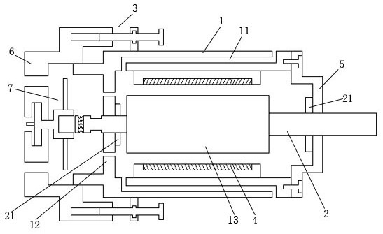
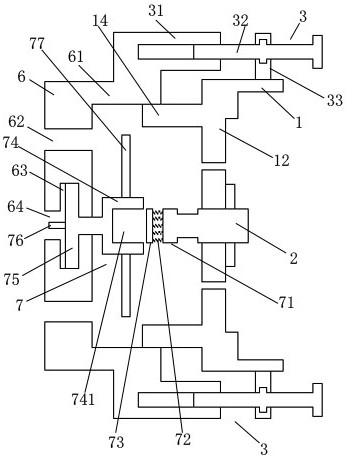
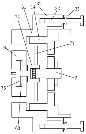
[0020] Such as Figures 1 to 5 As shown, a low-energy asynchronous motor includes an outer shell 1, a front end cover 5, a rear end cover 6, a rotating shaft 2, a stator 4, a plug-in linkage mechanism 7, and a rear end cover drive mechanism 3; the outer shell 1 The front end is fixedly installed with a front end cover 5; the stator 4 is installed around the inside of the outer casing 1; the rotating shaft 2 is connected to the inner shaft center of the outer casing 1; a cage rotor 13 is provided around the outer periphery of the rotating shaft 2, The cage rotor 13 is located inside the coaxial part of the stator 4; the front end of the rotating shaft 2 passes through the front end cover 5 and extends out; the rear end of the outer casing 1 is provided with a porous plate 12; the rear end of the rotating shaft 2 The end is pierced through the c...


PUM


Abstract

The invention discloses a low-energy-consumption asynchronous motor which comprises an outer shell, a front end cover, a rear end cover, a rotating shaft, a cage type rotor, a stator, an insertion linkage mechanism and a rear end cover driving mechanism. According to the invention, a traditional fixed connection structure of the rear end cover and the outer shell is changed. The rear end cover sleeves the inner core ring body on the outer side of the periphery of the rear end of the outer shell in a sliding manner through the sleeving ring body on the periphery of the inner end. In addition, the heat dissipation blades are rotationally connected to the interior of the rear end cover instead of being fixed to a rotating shaft traditionally. Meanwhile, a perforated plate for mounting the rear end of the rotating shaft is additionally arranged at the rear end of the outer shell. Therefore, when the rear end cover slides at the rear end of the outer shell, the rectangular insertion cavityof the rotating block is driven to be connected with the rectangular induction plate and the rectangular insertion block in an inserted or separated mode, whether the heat dissipation blades are in linkage with the rotating shaft or not is judged, and whether the heat dissipation blades are controlled to rotate or not can be determined according to the actual situation.

Description

technical field [0001] The invention relates to a low energy consumption asynchronous motor. Background technique [0002] Asynchronous motor is a kind of induction motor, which is a type of motor powered by simultaneous access to 380V AC current. Since the rotor and stator rotating magnetic field of a three-phase asynchronous motor rotate in the same direction and at different speeds, there is a slip. Therefore, it is called a three-phase asynchronous motor; the speed of the rotor of the three-phase asynchronous motor is lower than that of the rotating magnetic field, and the rotor winding generates electromotive force and current due to the relative motion between the rotor winding and the magnetic field, and interacts with the magnetic field to generate electromagnetic torque to realize energy conversion. ; On the rotating shaft of the existing motor, in order to facilitate heat dissipation, cooling blades will be installed at the rear end of the rotating shaft. When the...

Claims


Application Information

Patent Timeline
Patent Type & Authority Applications(China)
IPC IPC(8): H02K5/04H02K9/06
CPCH02K5/04H02K9/06
Inventor 吴领平
Owner 江苏美邦电机科技有限公司
Why Eureka
Try Eureka