Camera calibration method and terminal

A camera calibration and camera technology, applied in the field of image processing, can solve the problems of inconvenient selection of the origin of the world coordinate system, non-unique world coordinate system, and insignificant use of the world coordinate system.

Active Publication Date: 2020-07-28
SANLI VIDEO FREQUENCY SCI & TECH SHENZHEN
View PDF7 Cites 0 Cited by
  • Summary
  • Abstract
  • Description
  • Claims
  • Application Information

AI Technical Summary

Problems solved by technology

[0003] When using multiple cameras for data collection, there are the following problems: it is inconvenient to select the origin of the world coordinate system established by different cameras, and the obtained world coordinate system is not unique, resulting in little use of the world coordinate system; When locating objects in world coordinate linkage, multi-view projection geometry needs to be considered, and the model is complex

Method used


Image

  • Camera calibration method and terminal
  • Camera calibration method and terminal
  • Camera calibration method and terminal

Examples


Embodiment 1

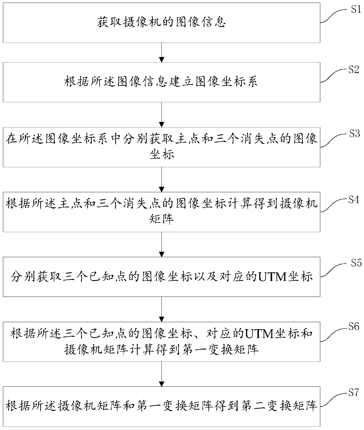
[0058] Please refer to figure 1 , Embodiment 1 of the present invention is a camera calibration method, comprising the following steps:

[0059] S1. Acquiring image information of a camera.

[0060] In this embodiment, it is assumed that the image captured by the camera has no radial distortion, and the camera is looking straight ahead and downward.

[0061] S2. Establish an image coordinate system according to the image information.

[0062] The coordinate origin of the image coordinate system can be set at the upper left corner of the picture, which can be a left-handed rectangular coordinate system or a right-handed rectangular coordinate system.

[0063] S3. Obtain the image coordinates of the main point and the three vanishing points respectively in the image coordinate system.

[0064] The main point can be freely selected, and the point in the center of the road can be selected, or the point not in the center of the road can be selected as the main point.

[0065] I...

Embodiment 2

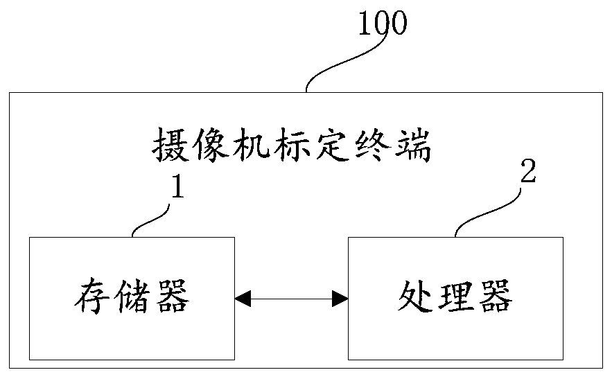
[0083] Please refer to figure 2 , the second embodiment of the present invention is:

[0084] A camera calibration terminal 100, corresponding to the method in Embodiment 1, includes a memory 1, a processor 2, and a computer program stored in the memory 1 and operable on the processor 2, and the processor 2 executes the When describing a computer program, the following steps are implemented:

[0085] Obtain the image information of the camera;

[0086] Establishing an image coordinate system according to the image information;

[0087] Obtaining the image coordinates of the main point and the three vanishing points respectively in the image coordinate system;

[0088] Calculate and obtain a camera matrix according to the image coordinates of the principal point and the three vanishing points;

[0089] Obtain image coordinates and corresponding UTM coordinates of three known points respectively;

[0090] Calculate the first transformation matrix according to the image coo...


PUM


Abstract

The invention discloses a camera calibration method and a terminal. The method comprises the following steps: acquiring image information of a camera; establishing an image coordinate system accordingto the image information; respectively obtaining image coordinates of a main point and three vanishing points in the image coordinate system; calculating to obtain a camera matrix according to the image coordinates of the main point and the three vanishing points; respectively acquiring image coordinates of the three known points and corresponding UTM coordinates; calculating to obtain a first transformation matrix according to the image coordinates of the three known points, the corresponding UTM coordinates and the camera matrix; and obtaining a second transformation matrix according to thecamera matrix and the first transformation matrix. According to the invention, automatic conversion between image coordinates and UTM coordinates can be realized, and linkage positioning of a plurality of cameras can be realized.

Description

technical field [0001] The present invention relates to the technical field of image processing, in particular to a camera calibration method and a terminal. Background technique [0002] As the cost of cameras and processors continues to drop, vision-based sensing is becoming an alternative to traditional sensors for collecting traffic data. Many research and commercial systems have obtained a series of interesting information through video analysis, such as road occupancy, vehicle speed, vehicle type, and event detection. [0003] When using multiple cameras for data collection, there are the following problems: it is inconvenient to select the origin of the world coordinate system established by different cameras, and the obtained world coordinate system is not unique, resulting in little use of the world coordinate system; When locating objects in conjunction with world coordinates, multi-view projection geometry needs to be considered, and the model is complex. Conte...

Claims


Application Information

Patent Timeline
Patent Type & Authority Applications(China)
IPC IPC(8): G06T7/80
CPCG06T7/80
Inventor 亢晓斌张宇刘东剑
Owner SANLI VIDEO FREQUENCY SCI & TECH SHENZHEN
Why Eureka
Try Eureka