Sliding compression type asynchronous motor

A kind of technology of asynchronous motor and compression type, which is applied in the direction of electric components, electrical components, electromechanical devices, etc., can solve the problems of increasing motor load, inflexible and changeable use, and increasing the difficulty of mold processing, etc., and achieves the effect of wide installation range

Inactive Publication Date: 2020-11-13
江苏美邦电机科技有限公司
View PDF0 Cites 0 Cited by
  • Summary
  • Abstract
  • Description
  • Claims
  • Application Information

AI Technical Summary

Problems solved by technology

[0002] Asynchronous motor is a kind of induction motor, which is a type of motor powered by simultaneous access to 380V AC current. Since the rotor and stator rotating magnetic field of a three-phase asynchronous motor rotate in the same direction and at different speeds, there is a slip. Therefore, it is called a three-phase asynchronous motor; the speed of the rotor of the three-phase asynchronous motor is lower than that of the rotating magnetic field, and the rotor winding generates electromotive force and current due to the relative motion between the rotor winding and the magnetic field, and interacts with the magnetic field to generate electromagnetic torque to realize energy conversion. ; On the rotating shaft of the existing motor, in order to facilitate heat dissipation, cooling blades will be installed at the rear end of the rotating shaft. When the shaft load is small, the cooling blades are not needed to blow and dissipate heat under the condition of good heat generation. In this case, the rotating shaft keeps driving the cooling blades to rotate, which is actually an additional load and increases the load on the motor. , so it is necessary to develop a motor that can open and close the heat dissipation blades according to actual needs; in addition, the existing front and rear end covers are generally fixed with the connecting ring rotating on the rotating shaft, so it is necessary to pre-precisely calculate the front and rear end covers and the connecting ring The position of the body increases the difficulty of mold processing, and the use is not flexible and changeable

Method used


Image

  • Sliding compression type asynchronous motor
  • Sliding compression type asynchronous motor
  • Sliding compression type asynchronous motor

Examples


Embodiment Construction

[0020] The content of the present invention will be further described in detail below in conjunction with the accompanying drawings.

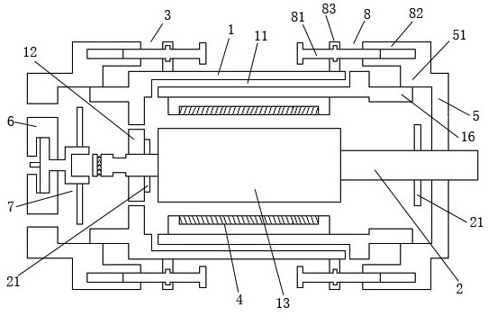
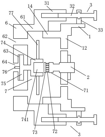
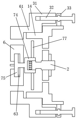
[0021] Such as Figures 1 to 5 As shown, a sliding compression asynchronous motor includes an outer shell 1, a front end cover 5, a rear end cover 6, a rotating shaft 2, a stator 4, a plug-in linkage mechanism 7, a rear end cover driving mechanism 3, and a front end cover driving mechanism 8. The inner end of the front end cover 5 is provided with a front end socket ring body 51; the outer front end of the outer shell 1 is provided with a front end inner core ring body 16; the front end cover 5 is connected through the front end socket around the inner end The ring body 51 is slidably socketed on the front end inner core ring body 16 around the front end of the outer shell 1; the front end cover drive mechanism 8 includes a front end threaded cylinder 82, a front end drive screw rod 81, and a front end positioning block 83; the front end cover ...


PUM


Abstract

The invention discloses a sliding compression type asynchronous motor. The motor comprises an outer shell, a front end cover, a rear end cover, a rotating shaft, a stator, an insertion linkage mechanism, a rear end cover driving mechanism and a front end cover driving mechanism. A front end cover is slidably connected to the outer side of the periphery of the front end of an outer shell in a sleeving mode through a front end cover driving mechanism. The front-end driving screw is clamped and rotated on the front-end positioning block, so that the front-end threaded cylinder is driven to move axially, the front-end cover is driven to be tightly connected to the connecting ring body of the rotating shaft in a pressed mode, the axial position is moved flexibly and variably due to the convenience of sliding connection, and therefore the installation range is wider and more flexible.

Description

technical field [0001] The invention relates to a sliding compression asynchronous motor. Background technique [0002] Asynchronous motor is a kind of induction motor, which is a type of motor powered by simultaneous access to 380V AC current. Since the rotor and stator rotating magnetic field of a three-phase asynchronous motor rotate in the same direction and at different speeds, there is a slip. Therefore, it is called a three-phase asynchronous motor; the speed of the rotor of the three-phase asynchronous motor is lower than that of the rotating magnetic field, and the rotor winding generates electromotive force and current due to the relative motion between the rotor winding and the magnetic field, and interacts with the magnetic field to generate electromagnetic torque to realize energy conversion. ; On the rotating shaft of the existing motor, in order to facilitate heat dissipation, cooling blades will be installed at the rear end of the rotating shaft. When the sh...

Claims


Application Information

Patent Timeline
IPC IPC(8): H02K5/04H02K9/06
CPCH02K5/04H02K9/06
Inventor 吴领平
Owner 江苏美邦电机科技有限公司
Why Eureka
Try Eureka