
Indoor and outdoor ultra-thin type electric energy-saving heating assembly

An ultra-thin, indoor and outdoor technology, applied in electric heating systems, space heating and ventilation details, household heating, etc., can solve the problem of reducing the effective height of the indoor space, the stability of the floor decoration cannot be guaranteed, and the flatness is not good, etc. question

Pending Publication Date: 2019-10-29
张广彦
View PDF0 Cites 1 Cited by
  • Summary
  • Abstract
  • Description
  • Claims
  • Application Information

AI Technical Summary

Problems solved by technology

However, there are still many problems in the development of water floor heating heating system today: 1. Water floor heating uses coal or natural gas as the heating heat source, which causes a lot of heat energy loss and inconvenient temperature control; 2. After long-term operation of water floor heating, the heating pipe will accumulate A large amount of scale will increase the resistance in the pipe, reduce the heat dissipation capacity, and the process of removing scale is complicated, which will also cause certain damage to the heating pipe, which will directly lead to the reduction of the service life of the water floor heating; 3. The laying of the water floor heating needs to occupy a certain height space in the room ; 4. Water floor heating must be buried under the indoor floor before the indoor floor decoration board is laid. If the indoor floor needs to be installed after the floor decoration board is laid, the floor decoration board must be removed for installation. After installing water floor heating on the laid floor decoration board and then re-laying the floor decoration board, the stability of the re-laid floor decoration cannot be guaranteed. On the other hand, the laying of water floor heating needs to occupy a certain height space in the room. Installing water floor heating on the floor decoration board and then re-laying the floor decoration board will reduce the indoor effective height and use space
The electric floor heating structure in the prior art consists of base layer, insulation layer, electric heating layer, leveling layer, and ground decoration panel layer from bottom to top. Among them, the leveling layer is generally laid with cement mortar or cement concrete, so the leveling layer needs more Second leveling, complex and cumbersome construction and poor flatness
The thickness of the leveling layer is generally 5 to 8 cm. Because there is a fault in the insulation layer on the base layer, a thick leveling layer must be used to effectively avoid serious hollowing and floor brick breakage due to long-term heating of the electric floor heating structure. But the thick leveling layer has caused the following problems at the same time: 1. The heat generated by the electric heating layer must first heat the thick leveling layer, and the ground decorative panel layer can only be heated after the temperature of the leveling layer rises. The heat cannot be dissipated quickly; 2. It reduces the indoor effective height utilization space
The above-mentioned carbon fiber electric heating system, graphene electric heating system and carbon crystal electric heating system do not have an independent ground wire, which is a great safety hazard for personal safety. Once leakage occurs, it will cause serious consequences, especially not suitable for bathroom space
The maximum length of a single group of carbon fiber heating cables in the prior art is only 12.5 meters. If the indoor space is large, several groups of carbon fiber heating cables need to be connected through the connectors, and several groups of carbon fiber heating cables are prone to leakage through the joints.

Method used


Image

  • Indoor and outdoor ultra-thin type electric energy-saving heating assembly
  • Indoor and outdoor ultra-thin type electric energy-saving heating assembly
  • Indoor and outdoor ultra-thin type electric energy-saving heating assembly

Examples


Embodiment 1

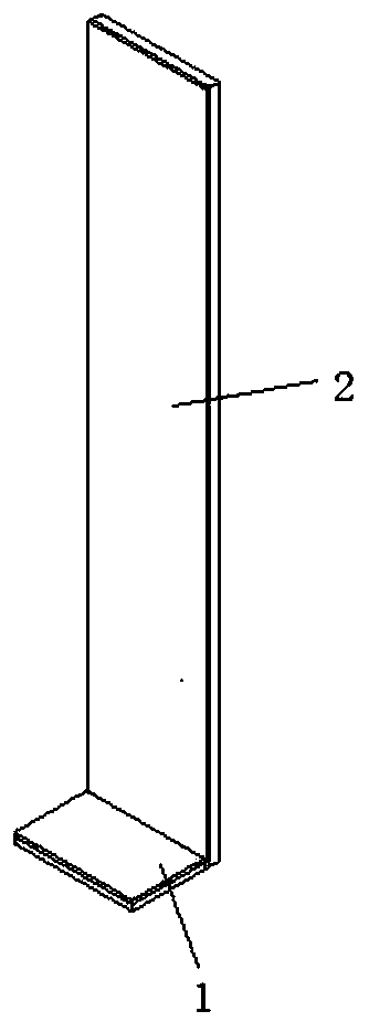
[0093] like figure 1 As shown, the indoor and outdoor ultra-thin electric energy-saving heating components include a floor heating unit 1 and a wall heating unit 2 .

[0094] like figure 2 As shown, the floor heating unit 1 includes a ground base leveling layer 101 , a ground insulation layer 102 , a ground wire mesh layer 103 , a ground cement bonding leveling layer 104 , and a ground decorative panel layer 105 that are sequentially attached from bottom to top.

[0095] like image 3 As shown, the wall heating unit 2 includes a wall base leveling layer 201 , a wall insulation layer 202 , a wall wire mesh layer 203 , a wall cement bonding leveling layer 204 , and a wall decoration panel layer 205 that are arranged sequentially.

[0096] Wherein, the thickness of the ground insulation layer 102 and the thickness of the wall insulation layer 202 are both less than 1 cm.

[0097] In this embodiment, there is no special requirement for the material of the ground base leveling ...

Embodiment 2

[0140] The indoor and outdoor ultra-thin electric energy-saving heating assembly in Embodiment 1 further includes a thermostat group, and the thermostat group respectively controls the first electric heating wire layer and the second electric heating wire layer. The temperature controller group is used to control the working state of the first electric heating wire layer and the second electric heating layer.

[0141] The thermostat group in this embodiment includes four thermostats, namely thermostat A5, thermostat B6, thermostat C7, thermostat D8; thermostat A5, thermostat B6, thermostat Both the controller C7 and the temperature controller D8 are fixed on the side wall of the wall decoration panel layer 205 facing away from the wall cement bonding leveling layer 204 .

[0142] The temperature controller A5 and the temperature controller B6 are used to control the working state of the first electric heating wire layer, and the temperature controller C7 and the temperature co...

Embodiment 3

[0149] The indoor and outdoor ultra-thin electric energy-saving heating assembly in Embodiment 1 further includes a thermostat group, and the thermostat group respectively controls the first electric heating wire layer and the second electric heating wire layer. The temperature controller group is used to control the working state of the first electric heating wire layer and the second electric heating layer.

[0150] The temperature controller group in this embodiment includes two temperature controllers, namely the temperature controller E9 and the temperature controller F10.

[0151] The U-shaped electric heating wire C230 laid in each U-shaped wiring groove C214 in the wall heating unit 2 is sequentially connected in series through the arc-shaped electric heating wire C238 to form a first-level electric heating wire layer, and each U-shaped electric heating wire in the wall heating unit 2 The U-shaped electric heating wire E232 laid in the wiring groove E218 is connected i...


PUM


Abstract

The invention discloses an indoor and outdoor ultra-thin type electric energy-saving heating assembly. The indoor and outdoor ultra-thin type electric energy-saving heating assembly comprises single or multiple spliced floor heating units and single or multiple spliced wall heating units, wherein the thickness of the floor heating units and the wall heating units is less than three centimeters; each wall heating unit comprises a wall substrate leveling layer, a wall thermal insulation layer, a wall silk screen layer, a wall cement bonding leveling layer and a wall decoration face board layer which are sequentially arranged in an attached mode from bottom to top; and each floor heating unit comprises a ground substrate leveling layer, a ground thermal insulation layer, a ground silk screenlayer, a ground cement bonding leveling layer and a ground decoration face board layer which are sequentially arranged in an attached mode from bottom to top. According to the indoor and outdoor ultra-thin type electric energy-saving heating assembly, the requirements of users for floor heating and wall heating can be met at the same time, the thickness of the floor heating units and the thicknessof the wall heating units are greatly reduced, so that the heating speed of the floor heating units and the wall heating units is increased, the heating effect is good, the temperature control is convenient and flexible, and the influence on the indoor effective use space is avoided.

Description

technical field [0001] The invention relates to the technical field of heating systems, in particular to indoor and outdoor ultra-thin electric energy-saving heating components. Background technique [0002] The existing indoor heating equipment is mainly electric heaters and heating air conditioners. The heating range of electric heaters and heating air conditioners is limited, which makes the heating of the whole room uneven, and consumes a lot of electricity, resulting in serious energy waste. [0003] The existing indoor centralized heating methods mainly include water floor heating, electric floor heating and radiator heating. The indoor environment temperature cannot be adjusted according to the needs of users through the heating method of radiators. There are many controlled factors, inflexibility, and a lot of energy waste. [0004] Water floor heating is used more and more because of its safety, no radiation, stable heating and other advantages. However, there ar...

Claims


Application Information

Patent Timeline
IPC IPC(8): F24D13/02F24D19/10
CPCF24D13/024F24D19/1096F24D2200/08Y02B30/00
Inventor 张广彦
Owner 张广彦
Learn More