Intelligent industrial robot positioning system

An industrial robot and positioning system technology, applied in the field of intelligent industrial robot positioning system, can solve the problems of unstable positioning system and inaccurate processing of workpieces by robots, and achieve the effect of accurate processing

Inactive Publication Date: 2020-11-27
吕永昭
View PDF0 Cites 1 Cited by
  • Summary
  • Abstract
  • Description
  • Claims
  • Application Information

AI Technical Summary

Problems solved by technology

[0003] The purpose of the present invention is to provide a positioning system for an intelligent industrial robot to solve the problem that the robot processes workpieces inaccurately due to the instability of the positioning system when the existing intelligent industrial robot proposed in the background technology is in use

Method used


Image

  • Intelligent industrial robot positioning system
  • Intelligent industrial robot positioning system
  • Intelligent industrial robot positioning system

Examples


Embodiment 1

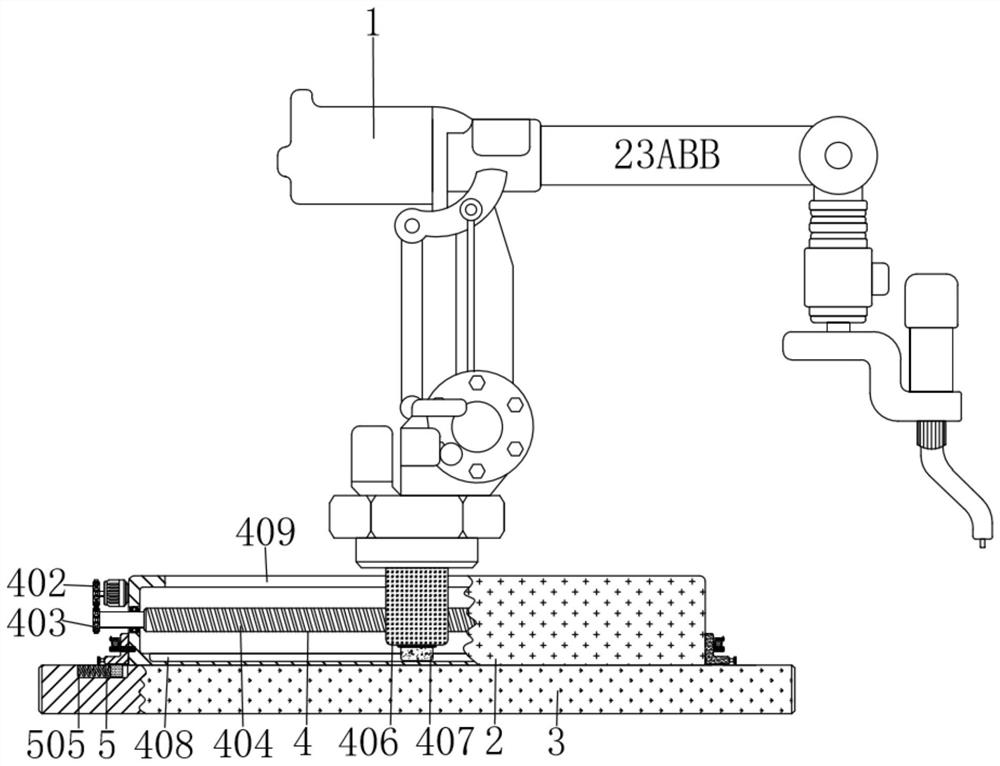
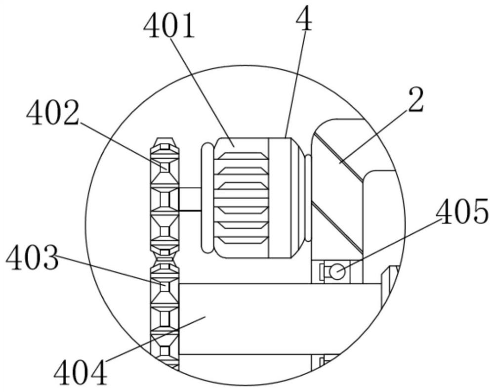
[0031]An intelligent industrial robot positioning system includes an industrial robot 1, a housing 2 is arranged under the industrial robot 1, a positioning mechanism 4 is installed inside the housing 2, and the positioning mechanism 4 includes a motor 401, a first gear 402, a second gear 402, threaded rod 404, bearing 405, vertical block 406, first slide block 407, first chute 408 and groove 409, the right end of motor 401 is fixedly connected with the top left end of housing 2, the output shaft of motor 401 is connected with the first The middle of the right end of a gear 402 is fixedly connected. The output shaft of the motor 401 drives the first gear 402 to rotate forward and reverse at a constant speed. The first gear 402 is meshed with the second gear 403. The force makes the second gear 403 rotate positively and negatively at a uniform speed. The middle of the right end of the second gear 403 is fixedly connected with the left end of the threaded rod 404. The threaded r...

Embodiment 2

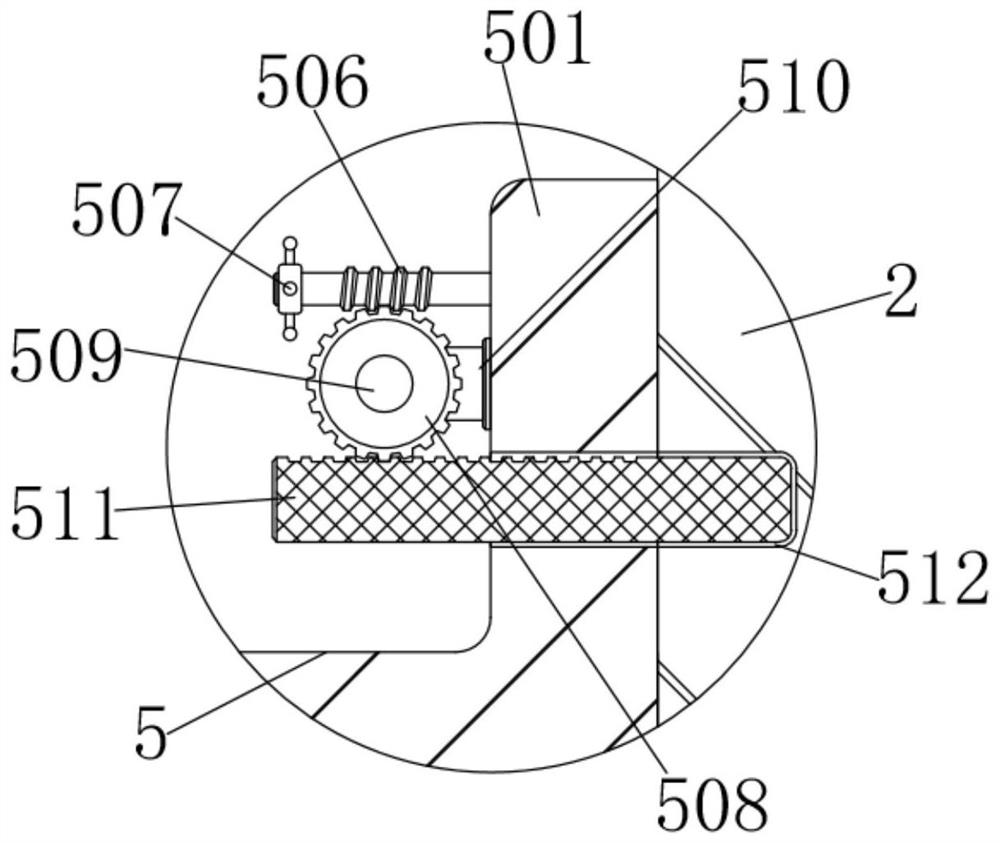
[0033] As an option, see figure 1 , 3 And 4, the intelligent industrial robot positioning system, the upper left and right sides of the bottom plate 3 are equipped with a fixed mechanism 5, the fixed mechanism 5 includes a splint 501, a handle 502, a second slider 503, a second chute 504, a spring 505, and a worm 506 , rotating rod 507, worm gear 508, pin shaft 509, support rod 510, cross bar 511 and draw-in groove 512, the right end of splint 501 and the lower left end of housing 2 fit together, and the bottom left side of splint 501 is provided with handle 502, A handle 502 is affixed to the lower left end of the splint 501, a second slider 503 is arranged in the middle of the bottom of the splint 501, the middle of the bottom of the splint 501 is fixedly connected with the top of the second slider 503, and the second slider 503 is connected to the second slider 503. The groove 504 is slidingly clamped, and the second sliding groove 504 is provided on the upper inner wall o...

Embodiment 3

[0036] The application of the intelligent industrial robot positioning system, when using the intelligent industrial robot positioning system, first manually drag the handles 502 on both sides to the outside so that the splints 501 on both sides pass through the second slider 503 on the second side of the bottom plate 3 sides respectively. The chute 504 slides to the outside, and the second sliders 503 on both sides move to the outside to compress the springs 505 on both sides, which can be adjusted according to the specifications of the housing 2 below the industrial robot 1. Otherwise, the elasticity of the springs 505 can make both sides The splint 501 clamps and fixes the shell 2 on the bottom plate 3, and the rotating rod 507 on both sides makes the worm 506 on both sides rotate on both sides of the splint 501 through the inner rubber pad, and the meshing between the worm wheel 506 and the worm wheel 508 The force makes the worm gears 508 on both sides rotate on the suppor...


PUM


Abstract

The invention discloses an intelligent industrial robot positioning system which comprises an industrial robot, wherein a shell body is arranged below the industrial robot; the right end of a motor isfixedly connected with the upper left end of the shell body; and an output shaft of the motor is fixedly connected with the middle of the right end of a first gear. According to the intelligent industrial robot positioning system, the left-right movement of the industrial robot can be stably and correctly positioned when the industrial robot is driven by a vertical block to move left and right ina groove of the shell body, an external workpiece can be correctly processed through the industrial robot, and the problem that when in use, a conventional intelligent industrial robot incorrectly processes a workpiece due to the instability of a positioning system can be solved; and the shell body is fixed on a baseplate by inserting transverse rods on two sides into clamping slots on two sidesof the shell body, so that the high mounting speed can be achieved, the working efficiency can be improved, and the problem that during the mounting of the conventional intelligent industrial robot, bolts and several other adopted components need to be connected, the mounting speed is low, and the working efficiency is influenced can be solved.

Description

technical field [0001] The invention relates to the technical field of industrial robots, in particular to an intelligent industrial robot positioning system. Background technique [0002] As an irreplaceable important equipment and means in the advanced manufacturing industry, intelligent industrial robots have become an important symbol to measure a country's manufacturing level and technological level. my country is in an important period of accelerating transformation and upgrading. The robot industry with industrial robots as the main body, It is an important path choice to solve the problems of rising industrial costs and environmental constraints in our country. However, when the existing intelligent industrial robots are in use, due to the unstable positioning system, the robots process the workpieces inaccurately. At the same time, there are existing intelligent industrial robots. When the robot is installed, it is connected by bolts and the like, and the installation...

Claims


Application Information

Patent Timeline
Patent Type & Authority Applications(China)
IPC IPC(8): B25J9/12B25J19/00
CPCB25J9/102B25J9/123B25J19/00
Inventor 吕永昭蔡佳豪
Owner 吕永昭
Why Eureka
Try Eureka