
Photovoltaic mounting bracket

A technology for installing brackets and photovoltaics, which is applied to the support structure of photovoltaic modules, photovoltaic power generation, photovoltaic modules, etc. It can solve the problems of large footprint of photovoltaic panels, installation of many photovoltaic panels, and inability to deploy photovoltaic panels conveniently. Simple structure, convenient for photovoltaic power generation

Active Publication Date: 2020-11-20
云晟(安徽)能源装备科技有限公司
View PDF4 Cites 2 Cited by
  • Summary
  • Abstract
  • Description
  • Claims
  • Application Information

AI Technical Summary

Problems solved by technology

[0002] In photovoltaic equipment, photovoltaic panels are common, and ordinary photovoltaic panels need to be installed in the working area with the help of brackets. The existing photovoltaic panel installation brackets have many disadvantages. A complete wrapping structure cannot be formed between them, which is extremely inconvenient during installation and placement, and since there is a gap between the photovoltaic panels after folding, there is no corresponding targeting for this gap in the prior art Design, so that the gap between the photovoltaic panels is small or no, so that the photovoltaic panels have gaps between each other after placement, so that after a large number of photovoltaic panels are placed, the overall footprint of the photovoltaic panels is larger. At this time it is not possible to install a large number of photovoltaic panels in a small area

Method used


Image

  • Photovoltaic mounting bracket
  • Photovoltaic mounting bracket
  • Photovoltaic mounting bracket

Examples


Embodiment Construction

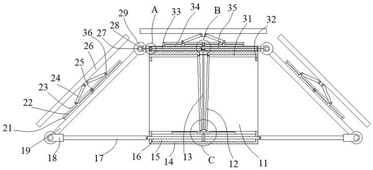
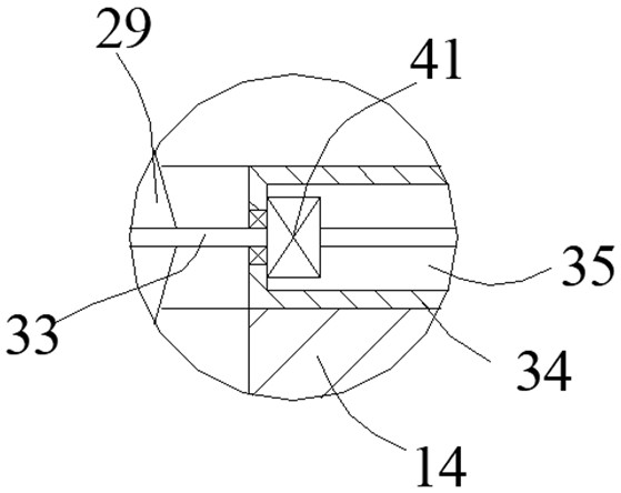
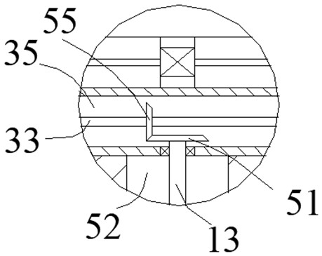
[0022] Such as Figure 1-Figure 4 As shown, the present invention is described in detail. For the convenience of description, the orientations mentioned below are now stipulated as follows: figure 1 The up, down, left, right, front and back directions of the projection relationship are the same. A photovoltaic installation bracket of the present invention includes a box body 14, and an inner cavity 11 is arranged in the box body 14, and a bottom inner cavity is connected to the lower end wall of the inner cavity 11. 15, the upper side of the inner cavity 11 is provided with a transmission inner cavity 35 located in the box body 14, and the rotation of the two sides of the box body 14 is provided with a rotation matching rod 19, and the rotation matching rod 19 and the box body 14 A telescopic photovoltaic panel device is provided on one side, and a drive locking device capable of swinging and telescopically locking the rotating matching rod 19 is provided in the box body 14 an...


PUM


Abstract

The invention discloses a photovoltaic mounting bracket. The photovoltaic mounting bracket comprises a box body, wherein an inner cavity is formed in the box body; a bottom inner cavity is formed in the lower end wall of the inner cavity in a communicating manner; a transmission inner cavity located in the box body is formed in the upper side of the inner cavity; rotation matching rods are rotationally arranged on the two sides of the box body; a telescopic photovoltaic panel device is arranged on one sides of the rotation matching rods and one side of the box body; and the box body and the inner cavity are internally provided with a driving locking device capable of enabling the rotating fit rod to swing and conduct telescopic locking. The photovoltaic mounting bracket is simple in structure, the photovoltaic panels can be turned over and folded to form a wrapping type structure, or the photovoltaic panels are spread to form an integrated structure after being unfolded, photovoltaic power generation of the photovoltaic panels is facilitated, and meanwhile a large number of photovoltaic panels can be installed on a small occupied area.

Description

technical field [0001] The invention relates to the technical field of photovoltaic equipment, in particular to a photovoltaic installation bracket. Background technique [0002] In photovoltaic equipment, photovoltaic panels are common, and ordinary photovoltaic panels need to be installed in the working area with the help of brackets. The existing photovoltaic panel installation brackets have many disadvantages. A complete wrapping structure cannot be formed between them, which is extremely inconvenient during installation and placement, and since there is a gap between the photovoltaic panels after folding, there is no corresponding targeting for this gap in the prior art Design, so that the gap between the photovoltaic panels is small or no, so that the photovoltaic panels have gaps between each other after placement, so that after a large number of photovoltaic panels are placed, the overall footprint of the photovoltaic panels is larger. In this case, it is not possib...

Claims


Application Information

Patent Timeline
IPC IPC(8): H02S20/30H02S30/20
CPCH02S20/30H02S30/20Y02E10/50
Inventor 陈骏卢慧慧陈羿霖
Owner 云晟(安徽)能源装备科技有限公司
Learn More