A Stress Uniform Optical Fiber Microbending Additional Loss Testing Device, System and Method

A technology of additional loss and testing equipment, which is applied in the direction of measuring equipment, optical instrument testing, and testing optical performance, etc., and can solve problems such as difficulty in accurate realization, poor operability, and greater influence on the control accuracy of rewinding equipment.

Active Publication Date: 2021-03-12
CHENGDU TAIRUI COMM EQUIP DETECTION
View PDF5 Cites 0 Cited by
  • Summary
  • Abstract
  • Description
  • Claims
  • Application Information

AI Technical Summary

Problems solved by technology

These methods have obvious shortcomings in practice. Method A has a complex mechanism and is not easy to realize accurately; method B has large differences in different batches of sandpaper, and the sand is easy to fall off, resulting in poor repeatability and is greatly affected by the control accuracy of the rewinding equipment; method D The operability is extremely poor; method C is difficult to reflect the difference in microbending sensitivity due to the short test distance and the use of sandpaper with minimal deformation

Method used


Image

  • A Stress Uniform Optical Fiber Microbending Additional Loss Testing Device, System and Method
  • A Stress Uniform Optical Fiber Microbending Additional Loss Testing Device, System and Method
  • A Stress Uniform Optical Fiber Microbending Additional Loss Testing Device, System and Method

Examples


Embodiment 1

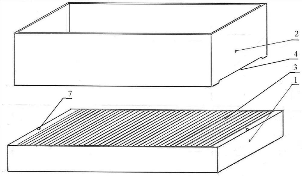
[0043] like figure 1 As shown, a stress-distributed optical fiber microbending additional loss testing device provided in this embodiment includes:

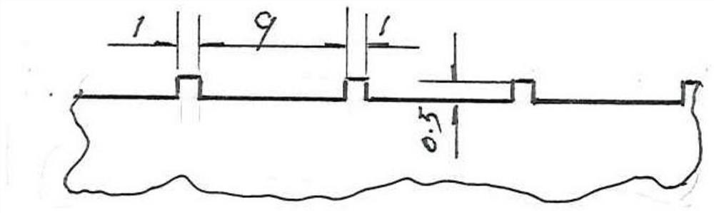
[0044] A grooved bottom plate and a water bag limiting frame 2, the upper surface of the grooved bottom plate is provided with a tooth groove 3 along the width direction;

[0045] When using the test device to test the tested optical fiber 6, the tested optical fiber 6 is placed on the bottom plate with a groove and the water bag limiting frame 2 is placed above the edge of the grooved bottom plate, and then placed on the water bag limiting frame 2. Entering the water bag 5, the measured optical fiber 6 is deformed along the shape of the alveolar 3 under the gravity of the water bag 5, thereby generating a slight bend.

[0046]In the testing device of the present embodiment, in order to make the tested optical fiber 6 produce the pressure of slight bending to be produced by the water bag 5 on the bottom plate with the groove, th...

Embodiment 2

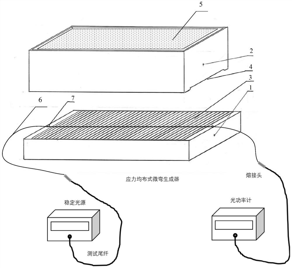
[0052] like image 3 As shown, this embodiment provides a stress-distributed optical fiber micro-bending additional loss testing system, including a stable light source, an optical power meter, and the stress-distributed optical fiber micro-bending additional loss testing device described in the embodiment.

[0053] The stress-distributed optical fiber micro-bending additional loss test method realized based on the test system can be divided into two types: one is to fill the water bag 5 with an appropriate amount of water, and then pack the water bag limit frame 2; the other The first is to arrange the water bag 5 in the water bag limiting frame 2, and then fill in an appropriate amount of water. They are as follows:

[0054] like Figure 4 As shown, the first stress-distributed optical fiber microbending additional loss testing method includes the following steps:

[0055] S11, placing the tested optical fiber 6 flatly on the grooved base plate, keeping the tested optical...


PUM

PropertyMeasurementUnit
radiusaaaaaaaaaa

Abstract

The invention discloses a stress uniform distribution type optical fiber micro-bending additional loss test device, a test system and a test method. The test device comprises a grooved bottom plate and a water bag limiting frame, and the upper surface of the grooved bottom plate is provided with a tooth groove along the width direction; when the test device is used for testing a tested optical fiber, a to-be-tested optical fiber is placed on the bottom plate with the groove, the water bag limiting frame is placed above the edge of the bottom plate with the groove, and then a water bag is placed in the water bag limiting frame, so that the to-be-tested optical fiber deforms along the shape of the tooth groove under the action of the gravity of the water bag containing water, and micro-bending is generated. According to the test device, the pressure used for enabling the to-be-tested optical fiber to generate micro-bending is generated by the water bag on the bottom plate with the groove, and the important problem in the IEC method can be effectively solved.

Description

technical field [0001] The invention relates to the technical field of optical fiber microbending additional loss testing, in particular to a stress uniform distribution type optical fiber microbending additional loss testing device, testing system and testing method. Background technique [0002] During the manufacture, installation and use of optical fiber cables, the optical fiber may be subjected to external pressure along the direction of the optical fiber, causing small, random, high-frequency micro-bending or bending of the optical fiber locally (usually the bending radius is not greater than 1mm) , resulting in a very small shift of the core relative to the fiber axis. This offset will cause the optical power transmitted inside the fiber to be coupled from the fundamental mode to the high-order mode, and mode coupling will occur, which will cause an increase in fiber loss, which is called fiber microbending additional loss, also known as fiber microbending sensitivit...

Claims


Application Information

Patent Timeline
Patent Type & Authority Patents(China)
IPC IPC(8): G01M11/02
CPCG01M11/02G01M11/0207
Inventor 薛梦驰左琼华宋志佗唐筱杨先金
Owner CHENGDU TAIRUI COMM EQUIP DETECTION
Why Eureka
Try Eureka