
LED driving module and illuminating lamp

A technology of driving modules and constant current modules, applied in the field of circuits, can solve the problems of high cost of linear constant current driving circuits, occupying a lot of space for lighting lamps, etc., and achieve the effects of low cost, avoiding stroboscopic linearity, and reducing loss.

Pending Publication Date: 2020-11-24
OPPLE LIGHTING ELECTRICAL ZHONG SHAN CO LTD +1
View PDF0 Cites 0 Cited by
  • Summary
  • Abstract
  • Description
  • Claims
  • Application Information

AI Technical Summary

Problems solved by technology

[0005] The present application discloses an LED drive module and a lighting fixture, so as to at least solve the problems of high cost of the existing linear constant current drive circuit and occupying a large amount of space of the lighting fixture

Method used


Image

  • LED driving module and illuminating lamp
  • LED driving module and illuminating lamp
  • LED driving module and illuminating lamp

Examples


Embodiment Construction

[0027] In order to make the purpose, technical solution and advantages of the present application clearer, the technical solution of the present application will be clearly and completely described below in conjunction with specific embodiments of the present application and corresponding drawings. Apparently, the described embodiments are only some of the embodiments of the present application, rather than all the embodiments. Based on the embodiments in this application, all other embodiments obtained by persons of ordinary skill in the art without making creative efforts belong to the scope of protection of this application.

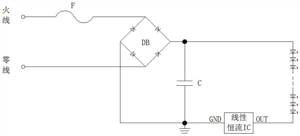
[0028] In order to solve the stroboscopic phenomenon caused by input voltage fluctuations, more and more lighting fixtures use linear constant current drive circuits, such as figure 1 As shown, the AC voltage is rectified by the rectifier bridge and then converted into a DC voltage input to the input terminal of the LED load to supply power for the LE...


PUM


Abstract

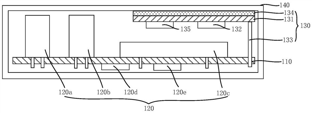
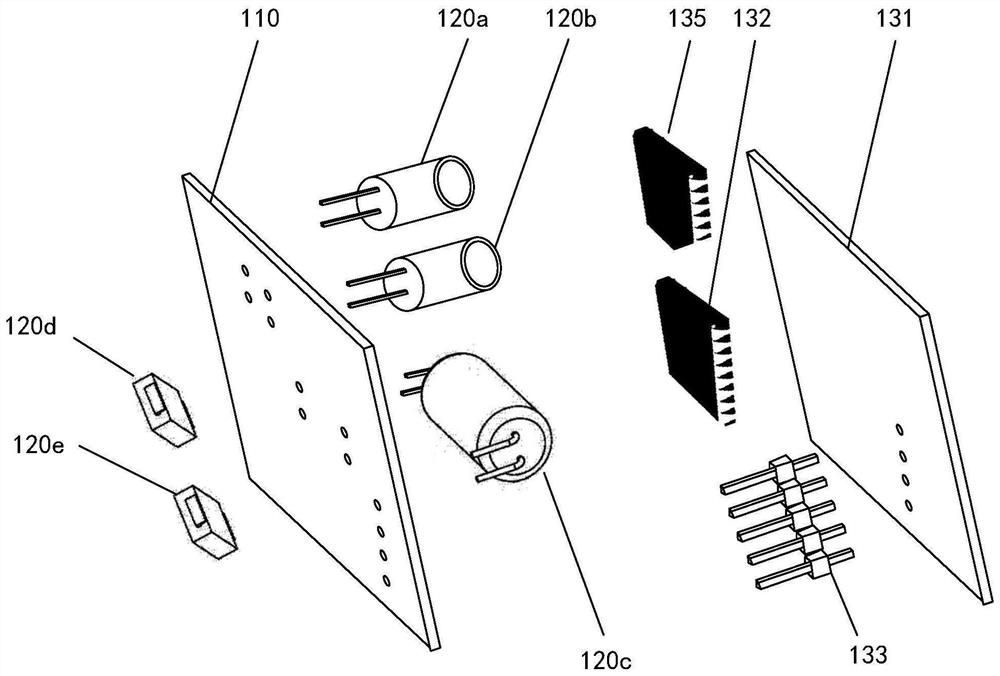
The invention discloses an LED driving module and an illuminating lamp, and aims to at least solve the problems that an existing linear constant-current driving circuit is high in cost and occupies alarge amount of space of the illuminating lamp. The LED driving module comprises a first substrate, an electronic component and a constant-current module; the electronic component is electrically connected with the input end of an LED load and drives the LED load, and the electronic component is arranged on the first substrate; the constant-current module is electrically connected with the outputend of the LED load and provides constant current for the LED load, the constant-current module at least comprises a second substrate and a constant-current IC chip, the constant-current IC chip is attached to the surface of the second substrate, and the second substrate is electrically connected with the first substrate.

Description

technical field [0001] The present application relates to the technical field of circuits, in particular to an LED driving module and a lighting fixture. Background technique [0002] In order to solve the stroboscopic phenomenon caused by input voltage fluctuations, more and more lighting fixtures use linear constant current drive circuits, by combining linear constant current ICs (Integrated Circuit, integrated circuits) connected in series to provide a constant current to the LEDs. [0003] Since the actual design of linear constant current drive needs to consider the input voltage range and strobe of the power grid, it is usually required that within the designed input voltage range, the minimum input voltage does not strobe, but at the maximum input voltage, the loss of the linear constant current drive circuit is relatively low. High, which requires high heat dissipation for the linear constant current drive circuit. [0004] In this regard, the circuit board of the ...

Claims


Application Information

Patent Timeline
Patent Type & Authority Applications(China)
IPC IPC(8): H05B45/345
CPCH05B45/345
Inventor 黎国权张国宝翁健峰
Owner OPPLE LIGHTING ELECTRICAL ZHONG SHAN CO LTD
Learn More