Supercharge Your Innovation With Domain-Expert AI Agents!

A pressure-balanced regulating ball valve

A balanced, regulating ball technology, applied in valve details, valve device, valve shell structure, etc., can solve the problems of inability to achieve pressure balance, increased manufacturing costs, large up and down strokes, etc., and achieves high pressure recovery coefficient and service life. Extends, reduces friction

Active Publication Date: 2022-07-05
KENZHUO AUTOMATIC CONTROL ENG (JIANGSU) CO LTD
View PDF12 Cites 0 Cited by
  • Summary
  • Abstract
  • Description
  • Claims
  • Application Information

AI Technical Summary

Problems solved by technology

On the one hand, the spool of this pressure balance regulating valve is driven by the actuator to move up and down, and the up and down stroke is large, so the cage and the valve body must have a certain height dimension, resulting in a large height and weight of the valve body, and increased manufacturing costs
On the other hand, the valve stem and the valve core are fixedly connected. Although the valve core can balance most of the force on the valve core by setting a balance hole, in principle it can reach a balanced state, but in fact it will still be affected by the valve stem. Influenced by the upward traction force, it cannot be completely free from force, that is, it cannot achieve a true pressure balance

Method used


Image

  • A pressure-balanced regulating ball valve
  • A pressure-balanced regulating ball valve
  • A pressure-balanced regulating ball valve

Examples


Embodiment Construction

[0015] In order to make the purposes, technical solutions and advantages of the embodiments of the present invention clearer, the technical solutions in the embodiments of the present invention will be clearly and completely described below with reference to the accompanying drawings in the embodiments of the present invention. Obviously, the described embodiments These are some embodiments of the present invention, but not all embodiments. Based on the embodiments of the present invention, all other embodiments obtained by persons of ordinary skill in the art without creative efforts shall fall within the protection scope of the present invention.

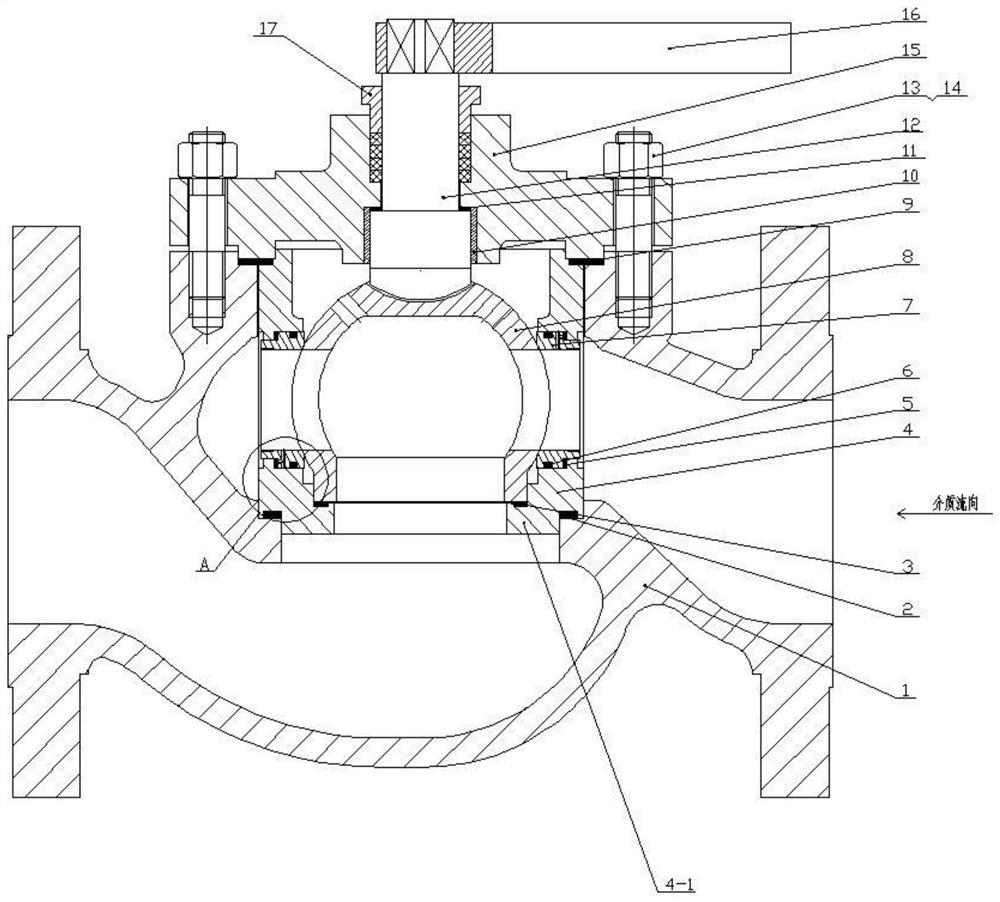
[0016] figure 1 and figure 2 A schematic structural diagram of a preferred embodiment of the present invention is shown. In the figure, a pressure-balanced regulating ball valve includes an upper valve cover 15, a valve body 1, a valve stem 12, a spherical valve core 8, a valve seat 7, and a valve The cage 4 and the driving dev...


PUM


Abstract

A pressure-balanced regulating ball valve, comprising an upper valve cover, a valve body, a valve stem, a spherical valve core, a valve seat, a valve cage and a driving device, at least two valve seats are arranged in the window of the valve cage and fixed by the spherical valve core , Between the valve seat and the valve cage, a sealing ring and a disc spring / cylindrical coil spring are sequentially installed from the inside to the outside; the spherical valve core is a hollow three-way sphere, and two side through holes are opened along the horizontal centerline on the hollow three-way sphere. , the lower end along the vertical centerline of the sphere is provided with a bottom through hole, the surface of the upper end is provided with an arc-shaped groove, both sides of the arc-shaped groove are provided with balance holes, one end of the valve stem is placed in the arc-shaped groove and floating connection, the other One end is connected to the drive device through the upper valve cover, and the valve stem is in sealing contact with the upper valve cover. The invention can use the ball valve as a regulating valve to avoid the adverse influence of medium force, and the volume, height and weight of the valve core and the valve body can be compacted and lightened, and the production cost can be saved.

Description

technical field [0001] The invention relates to a ball valve, in particular to a pressure-balanced and regulating ball valve. Background technique [0002] At present, it is well known that a ball valve is a valve with a ball as a closing member, and is mainly composed of a valve body, a valve seat, a ball, a valve stem, a handle (or other driving devices). The main function of the ball valve is to cut off or connect the fluid passage in the fluid passage in the pipeline, that is, the ball valve usually acts as a closed-circuit valve. Its working principle is: by means of a handle or other driving device, a certain torque is applied to the upper end of the valve stem and transmitted to the ball to make it rotate 90°. fully open or fully closed action. It can be seen that the ball valve can only be opened and closed, but cannot adjust the flow. The reason is that the pressure recovery coefficient is small and the anti-cavitation ability is weak, so it cannot be used as a re...

Claims


Application Information

Patent Timeline
Patent Type & Authority Patents(China)
IPC IPC(8): F16K5/06F16K5/08F16K27/06
CPCF16K5/0605F16K5/08F16K27/067
Inventor 严佳佳柴建民苏倩
Owner KENZHUO AUTOMATIC CONTROL ENG (JIANGSU) CO LTD
Features
  • R&D
  • Intellectual Property
  • Life Sciences
  • Materials
  • Tech Scout
  • Unparalleled Data Quality
  • Higher Quality Content
  • 60% Fewer Hallucinations
Learn More