Lifter with short mounting distance and large stroke

A technology with installation distance and large stroke, which is applied in the direction of lifting frame and lifting device, can solve the problems of increasing material cost, labor cost, reducing the volume of the lifting device, reducing the stability of the lifting device, and affecting the transmission efficiency, so as to reduce assembly failure and reduce The production cost and the effect of improving the transmission efficiency

Pending Publication Date: 2020-12-11
ZHEJIANG JIECHANG LINEAR MOTION TECH
View PDF1 Cites 1 Cited by
  • Summary
  • Abstract
  • Description
  • Claims
  • Application Information

AI Technical Summary

Problems solved by technology

[0004] This lifter has some disadvantages. Firstly, due to the large number of meshing pairs of worm gear and screw nut, its transmission efficiency is low; secondly, when the lifter needs to increase the stroke, it can only be achieved by increasing the number of screw rods and nuts. This will further affect its transmission efficiency, and at the same time increase the cost of materials, labor costs and the volume of the lifter, reducing the stability of the lifter

Method used


Image

  • Lifter with short mounting distance and large stroke
  • Lifter with short mounting distance and large stroke
  • Lifter with short mounting distance and large stroke

Examples


Embodiment 1

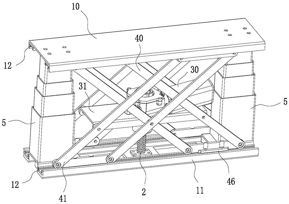
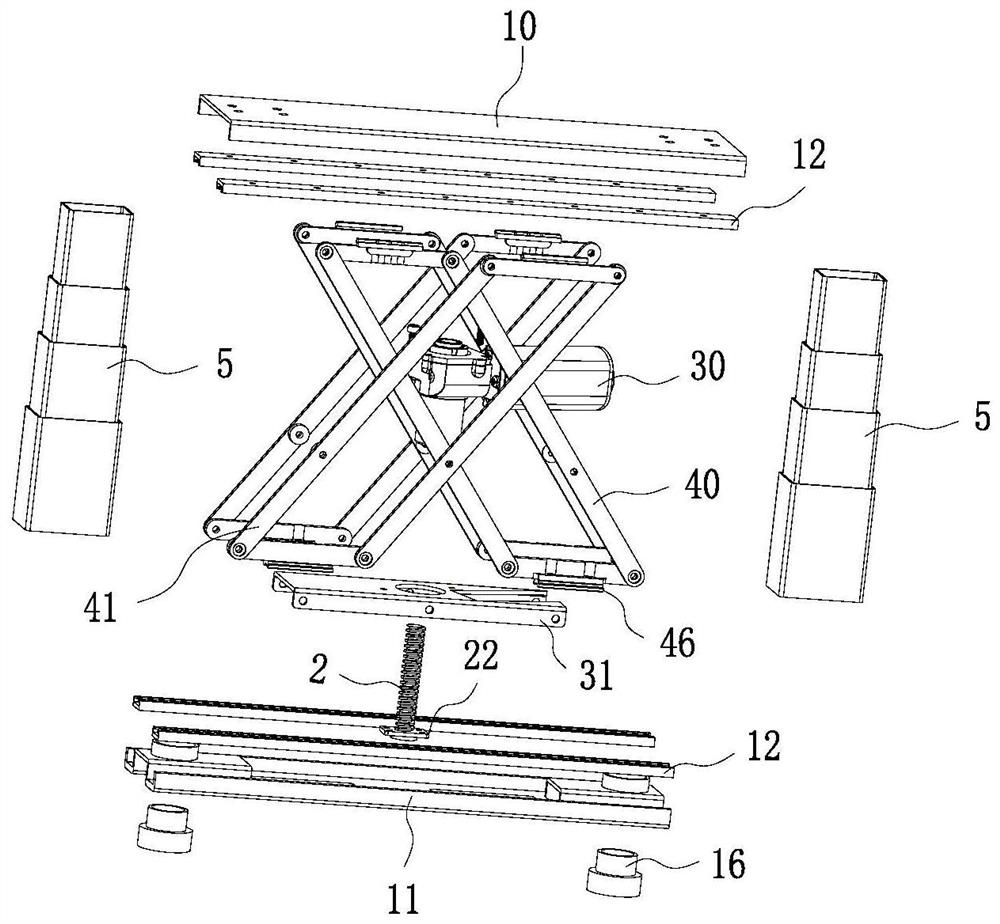
[0033] Such as Figure 1 to Figure 3 As shown, this embodiment shows a lifter with a low installation distance and a large stroke, including a top plate 10, a bottom plate 11 and a drive device for controlling the lifting of the top plate 10. The drive device includes a drive motor 30 and a drive motor 30. The screw mandrel 2 that is driven by the output shaft, the screw mandrel 2 is provided with a screw mandrel nut 21 matching with the thread of the screw mandrel, the drive device is fixed between the top plate 10 and the bottom plate 11, and the drive device is provided with a connection plate 31, a connecting rod set is arranged between the top plate 10 and the bottom plate 11, the two ends of the connecting rod set are respectively slidingly connected with the bottom plate 11 and the top plate 10, and the middle part of the connecting rod set is connected to the side of the connecting plate 31 by rotation. The driving device controls the lifting of the connecting plate 31...

Embodiment 2

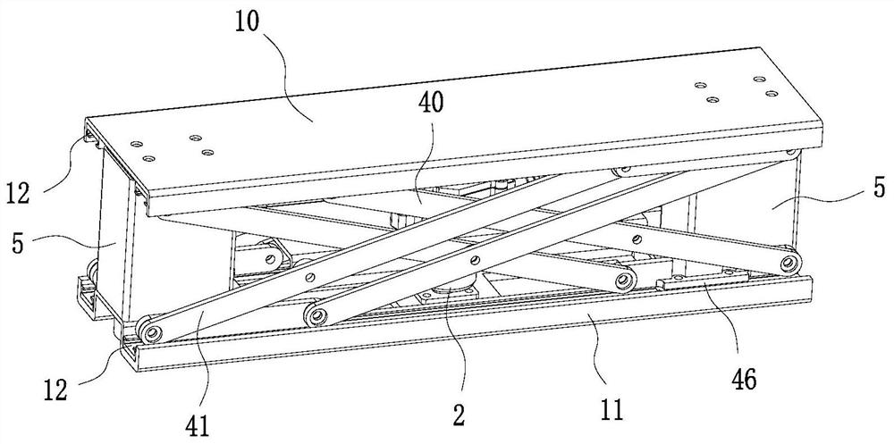
[0048] Such as Figure 4 to Figure 6 As shown, the main difference between this embodiment and Embodiment 1 is that the telescopic column 5 is omitted in this embodiment, and the linkage group includes an upper cross link 43 and a lower cross link 44, and the upper cross link The end of the rod 43 is rotatably connected with the end of the lower cross link 44, and the connection between the upper cross link 43 and the lower cross link 44 is connected with the connecting plate 31 through a rotating shaft, and the connecting plate 31 is provided with a The first chute 32 where the rotating shaft slides horizontally, the other end of the rotating shaft is provided with a first roller 45 that prevents the rotating shaft from detaching from the connecting plate 31, and the upper cross link 43 is hinged with one end of the top plate 10 to form a first hinged end 14, form a sliding connection with the other end of the top plate 10 through the cooperation of the second roller 47 and t...


PUM


Abstract

The invention provides a lifter with a short mounting distance and a large stroke. The lifter comprises a top plate, a bottom plate and a driving device used for controlling the top plate to ascend and descend, wherein the driving device comprises a driving motor and a lead screw, a lead screw nut is arranged on the lead screw, the driving device is fixed between the top plate and the bottom plate, a connecting plate is arranged on the driving device, connecting rod sets are arranged between the top plate and the bottom plate, the two ends of each connecting rod set are slidably connected withthe bottom plate and the top plate respectively, the middle of each connecting rod set is rotatably connected with the side face of the connecting plate, the driving device controls the connecting plate to ascend and descend, and the connecting plate drives the connecting rod set to move for ascending and descending of the top plate. The lifter has the advantages that the stroke of the lifter canbe increased by changing the connecting rod sets while the mounting distance is not increased.

Description

【Technical field】 [0001] The invention relates to a lifter with a low installation distance and a large stroke, which belongs to the technical field of lifting devices. 【Background technique】 [0002] As a lifting device, the lifter is widely used in kitchen, bathroom, office and other fields. The lifter in the prior art uses a drive motor to drive multiple screw rods, and the lifter is lifted by the transmission between the screw rod and the screw nut. , the lifting process is noisy and the transmission efficiency is low. In addition, the lifter also has the problems of large installation distance and small stroke. [0003] For example, the Chinese utility model patent CN206142728U discloses a lifter with an ultra-low installation distance. rod, wherein the first screw rod and the second screw rod are connected through a drive nut, and the lifter is driven by a driving mechanism to drive the first screw rod and the second screw rod respectively so as to realize the lifting...

Claims


Application Information

Patent Timeline
Patent Type & Authority Applications(China)
IPC IPC(8): B66F7/06B66F7/28
CPCB66F7/0608B66F7/0658B66F7/0666B66F7/28
Inventor 何立东程云山
Owner ZHEJIANG JIECHANG LINEAR MOTION TECH
Why Eureka
Try Eureka