
Air foot

An air foot and sufficient technology, applied in the field of air foot, can solve the problems of uneven deformation, unstable air foot performance and high processing cost, and achieve the effects of uniform deformation, stable air flotation performance and low processing cost.

Active Publication Date: 2020-12-11
YINGUAN SEMICON TECH CO LTD
View PDF12 Cites 3 Cited by
  • Summary
  • Abstract
  • Description
  • Claims
  • Application Information

AI Technical Summary

Problems solved by technology

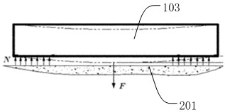
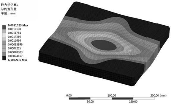
[0004] The characteristic of the above-mentioned square air foot structure in the prior art is that to increase the air flotation stiffness of the air foot, it is necessary to increase the air buoyancy force N and the vacuum preload force F at the same time, and increasing the vacuum preload force F will cause the air foot plate 103 to collapse. bending in the middle (eg figure 2 shown by the dotted line in ), as in image 3 As shown, the deformation of the air bearing structure 101 arranged at the four corners of the square air foot structure is uneven, resulting in unstable performance of the entire air foot, prone to air vibration or howling, thus affecting the performance of the precision transport platform
[0005] In the patent CN201110053278, aiming at the problem of uneven deformation of the square air foot, another air foot solution in this field is proposed
The invention provides a split-type air foot, the air flotation structure is separated from the vacuum preload structure, so as to avoid the bending deformation of the air foot plate when it is subjected to the vacuum preload force, and the impact on the air flotation area, but the air foot scheme The structure is very complicated, the processing cost is high, and the assembly and adjustment are difficult

Method used


Image

  • Air foot
  • Air foot
  • Air foot

Examples


Embodiment Construction

[0041] In order to make the purpose, technical solutions and advantages of the embodiments of the present invention more clear, various implementation modes of the present invention will be described in detail below in conjunction with the accompanying drawings. However, those of ordinary skill in the art can understand that, in each implementation manner of the present invention, many technical details are provided for readers to better understand the present application. However, even without these technical details and various changes and modifications based on the following implementation modes, the technical solution claimed in this application can also be realized.

[0042] In the following description, for the purposes of explaining the various disclosed embodiments, certain specific details are set forth in order to provide a thorough understanding of the various disclosed embodiments. One skilled in the relevant art will recognize, however, that an embodiment may be p...


PUM


Abstract

The invention discloses an air foot. The air foot comprises an air foot body, the air foot body is in a rectangular plate shape, and chamfered faces are arranged at the four corners of a rectangular plate; a first annular air leakage groove and a second annular air leakage groove are formed at the bottom face of the air foot body, the first annular air leakage groove and the second annular air leakage groove are coaxially formed and are spaced inwards in the radial direction relative to the second annular air leakage groove, and an air floating area is formed between the first annular air leakage groove and the second annular air leakage groove; the bottom surface of the rectangular air foot body is further provided with a vacuum preloading area located in the second annular air leakage groove; each side face and / or each chamfered face of the air foot body are / is provided with an air leakage port; a plurality of air leakage channels communicated with the first annular air leakage groove and the second annular air leakage groove are formed in the air foot body; the plurality of air leakage channels are respectively communicated with the air leakage ports; and compared with the priorart, the air foot is stable in performance, simple in structure, convenient to install and use and low in machining cost.

Description

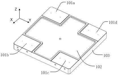
technical field [0001] Embodiments of the present invention relate to the technical field of precision equipment, in particular to air feet. Background technique [0002] The air foot is a key component that provides air bearing support for the precision motion table to ensure the frictionless movement of the motion table on the platform (usually a marble platform), which includes an air flotation structure and a vacuum preload structure. [0003] figure 1 Shown is a square air foot in the prior art. The four corners of the bottom surface of the air foot plate 103 of the square air foot are air flotation structures 101a, 101b, 101c, 101d, and the center is a vacuum preload structure 102. The structures 101 a , 101 b , 101 c , 101 d and the vacuum pretensioning force structure 102 are processed into one body by the air foot plate 103 . As shown in Fig. 2, when the air foot is working, the air flotation structures 101a, 101b, 101c, and 101d are injected with positive pressur...

Claims


Application Information

Patent Timeline
Patent Type & Authority Applications(China)
IPC IPC(8): F16C32/06
CPCF16C32/0614F16C32/0603F16C32/0662
Inventor 江旭初袁嘉欣吴火亮
Owner YINGUAN SEMICON TECH CO LTD
Learn More