Cantilever spring for impacted molar tooth traction, impacted tooth traction device and impacted tooth traction method

A traction device and impacted tooth technology, applied in dentistry, orthodontics, prosthetics, etc., can solve the problems of high treatment cost, waste of autologous teeth, inaccurate curative effect, etc. The effect of shortening the treatment time

Active Publication Date: 2020-12-15
SICHUAN UNIV
View PDF17 Cites 0 Cited by
  • Summary
  • Abstract
  • Description
  • Claims
  • Application Information

AI Technical Summary

Problems solved by technology

[0004] The first solution: expect the natural eruption of the impacted third molars to replace the missing second molars. Three molars
[0005] The second solution: first extract the impacted third molars, and then implant the second molars, but the disadvantages of this solution are also obvious, the treatment cost is relatively high, and at the same time, the patients bear the risk of implant treatment, which is a waste of patients Autologous teeth that are intact and can perform normal functions (that is, the extracted impacted third molars)
[0014] 1. Only applicable to high impacted third molars, not for low impacted third molars;
[0015] 2. It can only provide distal and vertical correction force, and the mesial movement is still required in the later stage, and the mesial movement of molars is the difficulty of orthodontic treatment;
[0016] 3. Some existing methods use adjacent teeth as anchorage, and adjacent teeth may tilt and move unnecessarily

Method used


Image

  • Cantilever spring for impacted molar tooth traction, impacted tooth traction device and impacted tooth traction method
  • Cantilever spring for impacted molar tooth traction, impacted tooth traction device and impacted tooth traction method
  • Cantilever spring for impacted molar tooth traction, impacted tooth traction device and impacted tooth traction method

Examples


Embodiment Construction

[0067] Embodiments of the present invention are described in detail below, examples of which are shown in the drawings, wherein the same or similar reference numerals designate the same or similar elements or elements having the same or similar functions throughout. The embodiments described below by referring to the figures are exemplary and are intended to explain the present invention and should not be construed as limiting the present invention.

[0068] In the description of the present invention, it should be noted that when an element is referred to as being “fixed” or “disposed on” another element, it may be directly on the other element or indirectly on the other element. When an element is referred to as being "connected to" another element, it can be directly connected to the other element or indirectly connected to the other element.

[0069] It is to be understood that the terms "length", "width", "top", "bottom", "front", "rear", "left", "right", "vertical", "hor...


PUM


Abstract

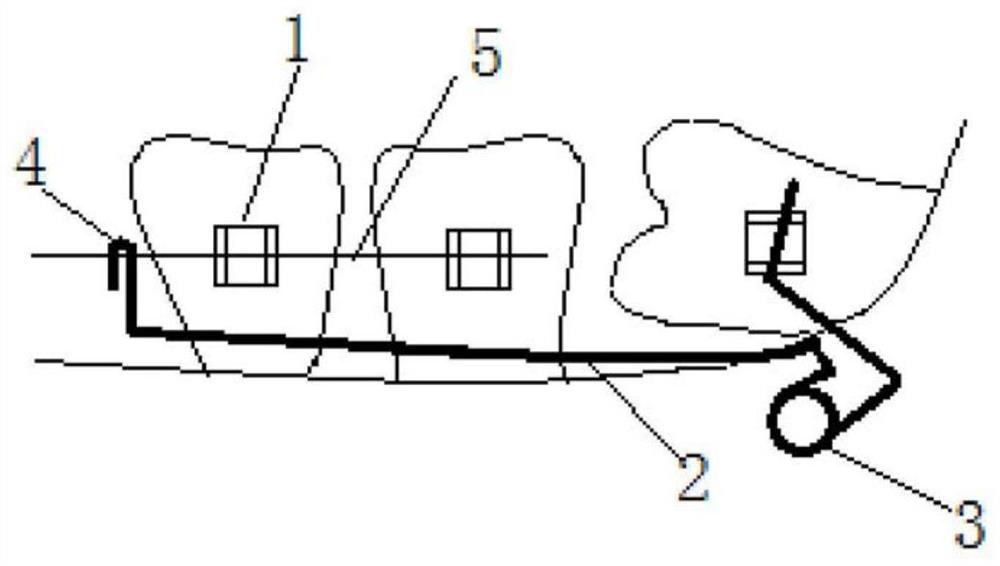
The invention is applicable to the technical field of orthodontics, and provides a cantilever spring for impacted tooth traction, an impacted tooth traction device and an impacted tooth traction method, wherein the cantilever spring comprises a first fixing part, a second fixing part, a first loop, a second loop, a first force arm, a second force arm and a third force arm; the first fixing part and the second fixing part are positioned at two ends; the fixation of the cantilever spring is realized through the first fixing part and the second fixing part; the first loop and the second loop format least one loop; the first force arm is formed between the first fixing part and the first loop; the second force arm is formed between the first loop and the second loop; and the third force arm is formed between the second loop and the second fixing part. According to the invention, strong anchorage is provided through a temporary anchorage device, so that no influence is caused on an adjacent tooth; the indications are wide; applicability to high-position or low-position impacted maxillary and mandibular third molar teeth is realized; in addition, the efficiency is sufficiently high; thedistal vertical and occlusal traction and proximal movement of the impacted third molar tooth can be performed at the same time; and the treatment course is greatly shortened.

Description

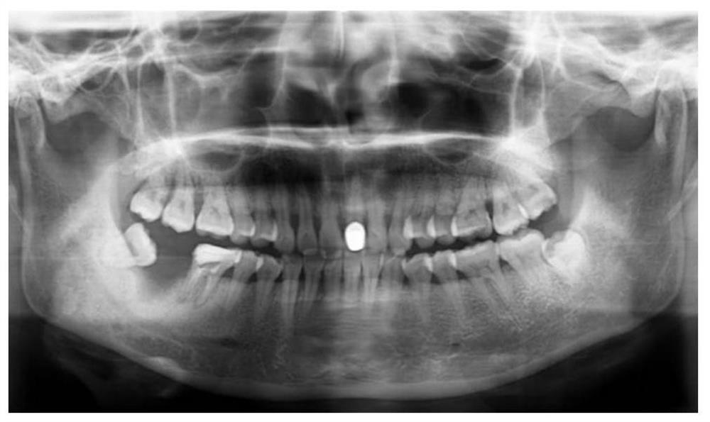
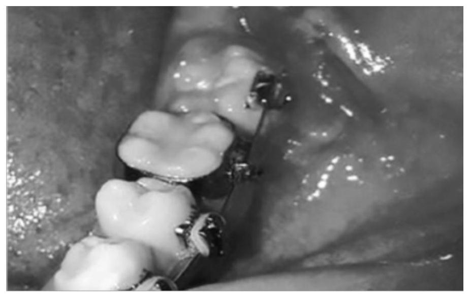
technical field [0001] The invention belongs to the technical field of orthodontics, and in particular relates to a cantilever spring, a traction device and a method for traction of impacted teeth. Background technique [0002] The impacted third molars often lead to serious endodontic diseases of the second molars, so the loss of the second molars, such as figure 1 A schematic representation of a missing second molar is shown. [0003] In the prior art, there are usually three solutions: [0004] The first solution: relying on the natural eruption of the impacted third molars to replace the missing second molars, but the course of treatment for this solution is too long, and the curative effect is too uncertain, especially for mandibular third molars. Three molars. [0005] The second solution: extract the impacted third molar first, and then implant the second molar, but the disadvantages of this solution are also obvious, the treatment cost is relatively high, and the ...

Claims


Application Information

Patent Timeline
Patent Type & Authority Applications(China)
IPC IPC(8): A61C7/00A61C7/10
CPCA61C7/00A61C7/10
Inventor 龙虎鄢鑫语刘璐周静张晓奇单迪邝芊允李晓龙简繁王艳刘显杨征赖文莉
Owner SICHUAN UNIV
Why Eureka
Try Eureka