Optical lens and imaging equipment

A technology of optical lens and imaging surface, which is applied in the direction of optics, optical components, instruments, etc., to achieve the effect of high pixel balance, meeting the needs of use, and small volume balance

Active Publication Date: 2021-02-05
JIANGXI LIANYI OPTICS CO LTD
View PDF4 Cites 0 Cited by
  • Summary
  • Abstract
  • Description
  • Claims
  • Application Information

AI Technical Summary

Problems solved by technology

However, in recent years, as consumers are keen on taking pictures with mobile phones, the high pixel of the rear camera has reached its peak. When developing towards a higher pixel, it will encounter the mutual constraints of thinner and lighter mobile phones and the limitation of the total length of the camera. Therefore, the ultra-wide-angle or even fish-eye lens on the rear of the mobile phone may become a wave; then how to achieve the balance of large wide-angle, high pixel and small size of the camera lens has become an urgent problem to be solved

Method used


Image

  • Optical lens and imaging equipment
  • Optical lens and imaging equipment
  • Optical lens and imaging equipment

Examples


no. 1 example

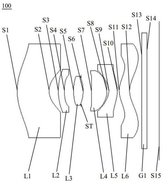
[0061] see figure 1 , which is a schematic diagram of the structure of the optical lens 100 provided by the first embodiment of the present invention, the optical lens 100 includes in sequence from the object side to the imaging surface along the optical axis: a first lens L1, a second lens L2, a third lens L3, Stop ST, fourth lens L4, fifth lens L5, sixth lens L6, and infrared filter G1.

[0062] The first lens L1 has negative refractive power, the object side S1 of the first lens is a convex surface, and the image side S2 of the first lens is a concave surface;

[0063] The second lens L2 has a negative refractive power, the object side S3 of the second lens is a convex surface, and the image side S4 of the second lens is a concave surface;

[0064] The third lens L3 has positive refractive power, the object side S5 of the third lens is convex, and the image side S6 of the third lens is convex;

[0065] The fourth lens L4 has positive refractive power, the object side S7 o...

no. 2 example

[0080] see Figure 5 , which is a schematic structural view of the optical lens 200 provided in this embodiment, the structure of the optical lens 200 in this embodiment is roughly the same as that of the optical lens 100 in the first embodiment, except that the sixth lens is a meniscus Type lenses, as well as the radius of curvature and material selection of each lens are different.

[0081] The relevant parameters of each lens in the optical lens 200 provided in this embodiment are shown in Table 3.

[0082] table 3

[0083]

[0084] The surface coefficients of each aspheric surface of the optical lens 200 in this embodiment are shown in Table 4.

[0085] Table 4

[0086]

[0087] Please refer to Figure 6 , Figure 7 and Figure 8 , respectively showing the field curvature curve, the on-axis point spherical aberration and the vertical axis chromatic aberration curve of the optical lens 200 .

[0088] Figure 6 The field curvature curve of represents the degree...

no. 3 example

[0092] see Figure 9 , which is a schematic structural view of the optical lens 300 provided in this embodiment, the structure of the optical lens 300 in this embodiment is roughly the same as that of the optical lens 100 in the first embodiment, the difference is that in this embodiment The object side surface S7 of the fourth lens L4 of the optical mirror 300 is a convex surface, and the curvature radius and material selection of each lens are different.

[0093] The relevant parameters of each lens in the optical lens 300 provided in this embodiment are shown in Table 5.

[0094] table 5

[0095]

[0096] Table 6 shows the surface coefficients of each aspheric surface of the optical lens 300 in this embodiment.

[0097] Table 6

[0098]

[0099] Please refer to Figure 10 , Figure 11 and Figure 12 , respectively showing the field curvature curve, the on-axis spherical aberration and the vertical axis chromatic aberration curve of the optical lens 300 .

[010...


PUM


Abstract

The invention discloses an optical lens and an imaging device. The optical lens comprises in sequence from the object side to the imaging surface: a first lens with negative optical power, the object side is convex, and the image side is concave; degree of the second lens, its object side is convex, its image side is concave; the third lens with positive power, its object side and image side are convex; stop; the fourth lens with positive power, its The image side is convex; the fifth lens with negative power, its object side is concave, and its image side is convex at the near optical axis; the sixth lens with negative power, its object side is at the near optical axis It is convex and its image side is concave near the optical axis. The above-mentioned optical lens, through reasonable matching of six lens shapes and focal powers with specific refractive power, makes the field of view of the optical lens reach more than 150°, and the total optical length is less than 6mm, which better realizes large wide-angle, small size and The balance of high pixels can effectively improve the user's camera experience.

Description

technical field [0001] The invention relates to the technical field of lens imaging, in particular to an optical lens and an imaging device. Background technique [0002] At present, with the popularization of portable electronic devices (such as smartphones, tablets, and cameras), coupled with the popularity of social, video, and live broadcast software, people are more and more fond of photography, and camera lenses have become a must for electronic devices. Standard configuration, camera lenses have even become the primary consideration for consumers when purchasing electronic equipment. [0003] With the continuous development of mobile information technology, portable electronic devices such as mobile phones are also developing in the direction of ultra-wide-angle and ultra-high-definition imaging, which puts forward higher requirements for camera lenses mounted on portable electronic devices. However, in recent years, as consumers are keen on taking pictures with mobi...

Claims


Application Information

Patent Timeline
Patent Type & Authority Patents(China)
IPC IPC(8): G02B13/00G02B13/06G02B13/18
CPCG02B13/0015G02B13/0045G02B13/06
Inventor 王义龙刘绪明曾昊杰曾吉勇
Owner JIANGXI LIANYI OPTICS CO LTD
Why Eureka
Try Eureka