Sample sock storage frame for hosiery machine

A rack and sample technology, applied in the direction of tool storage devices, manufacturing tools, etc., can solve the problems of workshop occupation, large space, inconvenient placement of sample socks, etc., and achieve the effect of convenient storage and retrieval

Inactive Publication Date: 2020-12-25
三门比忠纺织有限公司
View PDF0 Cites 0 Cited by
  • Summary
  • Abstract
  • Description
  • Claims
  • Application Information

AI Technical Summary

Problems solved by technology

After the hosiery machine is produced, the finished socks must be placed. During the use of the existing hosiery machine sample hosiery rack, it is inconvenient to place, take, check and compare the sample hosiery. At the same time, an existing The number of sample socks stored on the sample socks rack is not large, so it is required to install more hosiery machine placement devices in the workshop, which takes up a large space in the workshop. Therefore, some people propose a rack that can be turned sideways to store sample socks. Now Some shelves such as figure 1 As mentioned above, the bracket for placing sample socks is composed of a bottom plate 10 and a frame 20 with an L-shaped cross section. This kind of rack is inconvenient when placing sample socks, and it is necessary to improve it.

Method used


Image

  • Sample sock storage frame for hosiery machine
  • Sample sock storage frame for hosiery machine
  • Sample sock storage frame for hosiery machine

Examples


Embodiment Construction

[0021] The specific implementation manners of the present invention will be further described in detail below in conjunction with the accompanying drawings and embodiments. The following examples are used to illustrate the present invention, but are not intended to limit the scope of the present invention.

[0022] The following content reference Figure 2 to Figure 4 .

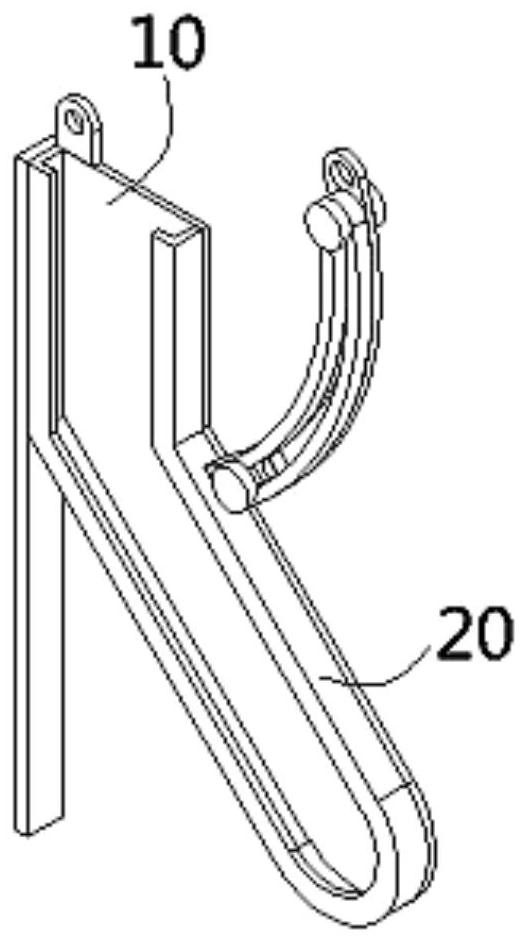
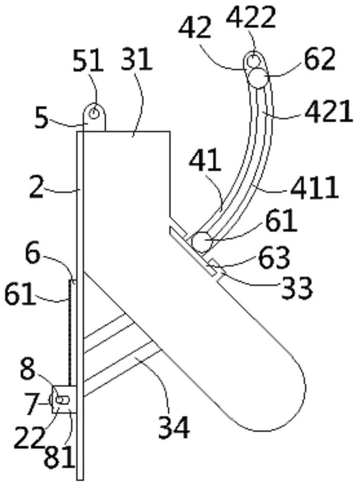
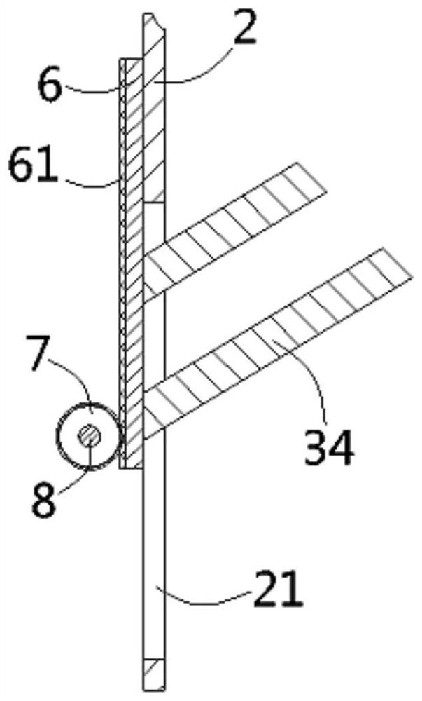
[0023] A sample sock rack for hosiery machines according to the present invention comprises a side-standing bottom plate 1, the bottom plate is composed of a vertical upper plate body 11 and an inclined lower plate body 12, the upper plate body A vertical positioning plate 2 is fixed on one side, and a transparent cover 3 is arranged on the bottom plate. The transparent cover is composed of a panel 31 having the same shape as the bottom plate and a rib 32 formed on the edge of the panel. Against the side of the bottom plate, one side of the bottom plate is provided with a circular arc-shaped moving overturn...


PUM


Abstract

The invention discloses a sample sock storage frame for a hosiery machine. The sample sock storage frame comprises a side-standing bottom plate, wherein a vertical positioning plate is fixed to one side of the bottom plate, a transparent cover shell is arranged on the bottom plate, a blocking edge abuts against the side edge of the bottom plate, and an arc-shaped movable overturning support and anarc-shaped fixed overturning support are arranged at one side of the bottom plate; the movable overturning support and the fixed overturning support abut against each other, the lower portion of themovable overturning support is fixed to the bottom plate, an arc-shaped movable sliding groove and an arc-shaped fixed sliding groove are formed in the movable overturning support and the fixed overturning support respectively, and a T-shaped lower magnet pin shaft is inserted into the lower end of the movable sliding groove and the lower end of the fixed sliding groove; a T-shaped upper magnet pin shaft is inserted into the upper end of the movable sliding groove and the upper end of the fixed sliding groove; and two inclined supporting columns are formed on the bottom face of the transparentcover shell, a vertical guide groove is formed in the positioning plate, the supporting columns penetrate through the guide groove and are fixed to a vertical lifting plate, a vertical rack is formedon the lifting plate, and a gear is meshed with the rack. According to the sample sock storage frame, sample socks can be conveniently stored and taken.

Description

technical field [0001] The invention relates to the technical field of hosiery machines, in particular to a sample hosiery rack for hosiery machines. Background technique [0002] The hosiery machine is a knitting machine that uses crochet to knit shaped socks to produce socks. The hosiery machine can be classified according to the form of the needle bed, the type of knitting needles and the number of cylinders. After the hosiery machine is produced, the finished socks must be placed. During the use of the existing hosiery machine sample hosiery rack, it is inconvenient to place, take, check and compare the sample hosiery. At the same time, an existing The number of sample socks stored on the sample socks rack is not large, so it is required to install more hosiery machine placement devices in the workshop, which takes up a large space in the workshop. Therefore, some people propose a rack that can be turned sideways to store sample socks. Now Some shelves such as figure 1...

Claims


Application Information

Patent Timeline
IPC IPC(8): B25H3/04
CPCB25H3/04
Inventor 毕卜存
Owner 三门比忠纺织有限公司
Why Eureka
Try Eureka