An ultra-high pressure small hydraulic press system

A hydraulic press and ultra-high pressure technology, applied in the field of ultra-high pressure small hydraulic press systems, can solve problems such as large weight and size, overall system size, large weight, and small pressing load, so as to improve installation efficiency and installation accuracy, overall size and weight The effect of shrinking and reducing the weight of the press

Active Publication Date: 2022-07-26
SHANGHAI MARINE EQUIP RES INST
View PDF12 Cites 0 Cited by
  • Summary
  • Abstract
  • Description
  • Claims
  • Application Information

AI Technical Summary

Problems solved by technology

The existing hydraulic press systems mainly have the following problems: 1) General large-tonnage hydraulic press systems generally use conventional pressure (not exceeding 70MPa). In order to obtain large-tonnage pressing force, the overall system size and weight are relatively large, and the integration Not high; 2) Generally, a booster cylinder is used to obtain higher pressure, and the high-pressure, large-size booster cylinder and its corresponding valve parts need to be specially made, and the versatility, interchangeability and maintainability are not good; 3) In order to achieve Fast-forward and fast-forward generally need to be equipped with a large flow pump and a small flow pump at the same time, resulting in a more complex hydraulic system, and a correspondingly larger weight and size; 4) The oil cylinder of the hydraulic press system is large in size, heavy in weight, and small in compression load
The oil cylinder adopts a general sealing ring, the oil pressure of the oil cylinder is low, and the oil cylinder cannot withstand ultra-high pressure above 100MPa
The oil cylinder is made of ordinary materials, with a larger volume and lower pressure

Method used


Image

  • An ultra-high pressure small hydraulic press system
  • An ultra-high pressure small hydraulic press system
  • An ultra-high pressure small hydraulic press system

Examples


Embodiment Construction

[0039] The following structural description drawings further describe the specific technical solutions of the present invention.

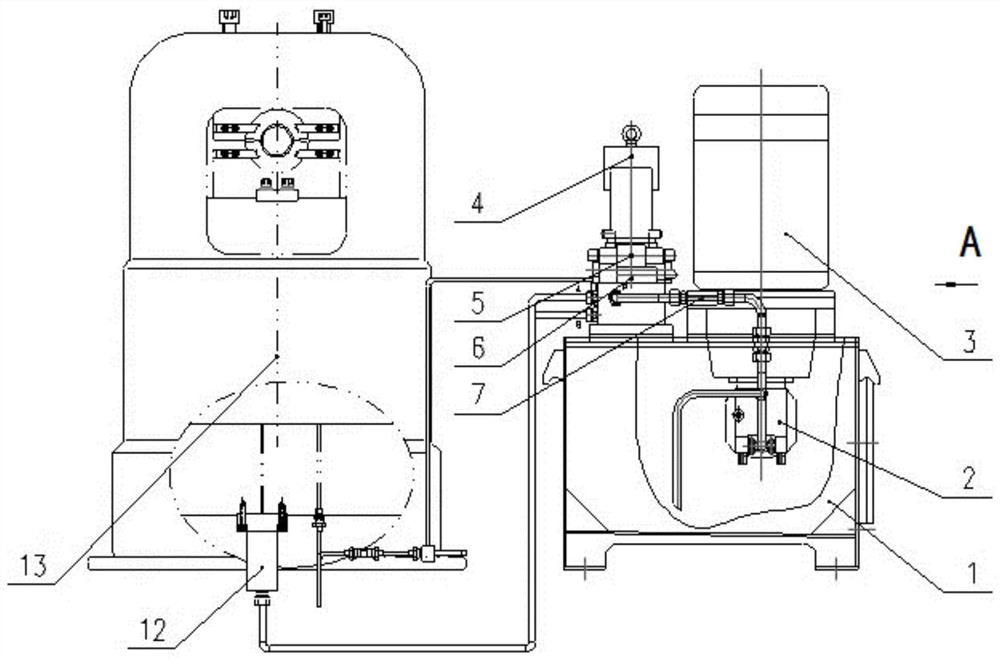
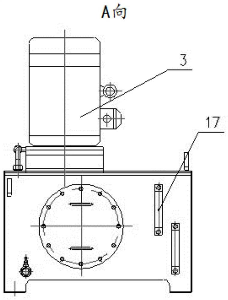
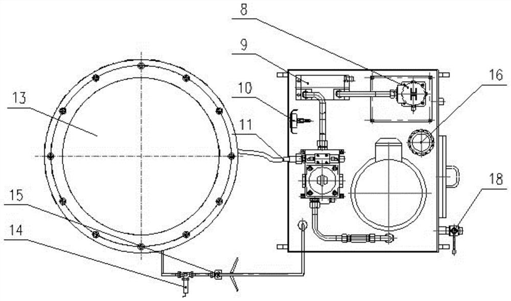
[0040] as attached Figure 1-5 As shown, an ultra-high pressure small hydraulic press system of the present invention mainly includes a fuel tank 1, a hydraulic pump 2, a motor 3, a pressure filter 4, an electromagnetic reversing valve 5, a relief valve 6, a one-way valve 7, and an oil return filter. 8, air cooler 9, pressure gauge 10, hose 11, supercharger 12, oil cylinder 13, pressure sensor 14, manual pressure relief valve 15, air filter 16, liquid level gauge 17, drain valve 18, clock shape cover 19, shock absorber ring 20 and coupling 21.

[0041] The oil tank 1 is welded by stainless steel plate, and the top plate of the oil tank has a flange hole; the motor 3, the bell 19 and the shock absorber ring 20 are connected to the flange hole of the oil tank 1 through bolts; the motor 3 is connected to the hydraulic pump 2 through the coupling 21 ...


PUM


Abstract

The invention provides an ultra-high pressure small hydraulic press system, which mainly includes an oil tank (1), a hydraulic pump (2), a motor (3), a pressure filter (4), an electromagnetic reversing valve (5), a relief valve ( 6), a one-way valve (7), a hose (11), a booster (12) and an oil cylinder (13), characterized in that the oil suction port of the hydraulic pump (2) is connected to the oil tank (1). ) connection, the oil cylinder (13) includes a cylinder barrel (1301), a plunger (1306), a cylinder head plate (1307), an inner snap ring (1308) and a base (1309), the supercharger (12) The oil outlet HP of ) is connected to the cylinder head plate (1307) of the oil cylinder (13) through a flange, and is connected to the rodless cavity of the oil cylinder (13) through the pressure hole of the cylinder head plate (1307). The ultra-high pressure small hydraulic press system of the present invention can provide continuous ultra-high hydraulic pressure and realize functions such as stepless pressurization, pressure maintenance at any time, and safe pressure relief. The oil cylinder is small in size, light in weight and easy to carry, and provides a pressing force for the pressing joint of the wire rope rigging.

Description

technical field [0001] The invention belongs to the technical field of hydraulic machinery, and in particular relates to an ultra-high pressure small hydraulic press system for pressing joints of wire rope riggings. Background technique [0002] The hydraulic press system uses hydraulic oil as the working medium and the hydraulic pump as the power source. The hydraulic oil enters the cylinder through the hydraulic pipeline by the force of the pump, and then there are several sets of mutually matched seals in the cylinder to make the hydraulic The oil cannot leak, and the mechanical action of the oil cylinder is used to circulate work to realize a series of functions such as mold clamping, mold clamping, and mold opening. [0003] Rigging hydraulic press system is mainly used to press wire rope rigging. The existing hydraulic press system mainly has the following problems: 1) The general-purpose large-tonnage hydraulic press system generally adopts conventional pressure (no ...

Claims


Application Information

Patent Timeline
Patent Type & Authority Patents(China)
IPC IPC(8): B30B1/32B30B15/02B21D39/00F15B15/14
CPCB30B1/32B30B15/026B21D39/00F15B15/1428
Inventor 郭晓波纪任锋李江涛徐小进高春晓
Owner SHANGHAI MARINE EQUIP RES INST
Why Eureka
Try Eureka