Light emitting diode lamp

A technology of light-emitting diodes and lamps, which is applied to illuminated signs, instruments, display devices, etc., and can solve problems such as heavy oily smoke and light-emitting areas of lamp beads

Inactive Publication Date: 2021-01-01
北京如利本辉科技有限公司
View PDF0 Cites 0 Cited by
  • Summary
  • Abstract
  • Description
  • Claims
  • Application Information

AI Technical Summary

Problems solved by technology

[0003] Due to the heavy oil fumes from the barbecue stand, grease will adhere to the LED lamp board placed next to the grill, and the LED lamp beads will generate heat when they are lit for a long time, so that the attached grease on the lamp beads will be heated and melted. Concentrated downward flow, long-term accumulation will cause a large amount of grease to concentrate at the lower end of the lamp bead, which will cause the light-emitting area of ​​the lamp bead to be blocked

Method used


Image

  • Light emitting diode lamp
  • Light emitting diode lamp
  • Light emitting diode lamp

Examples


Embodiment 1

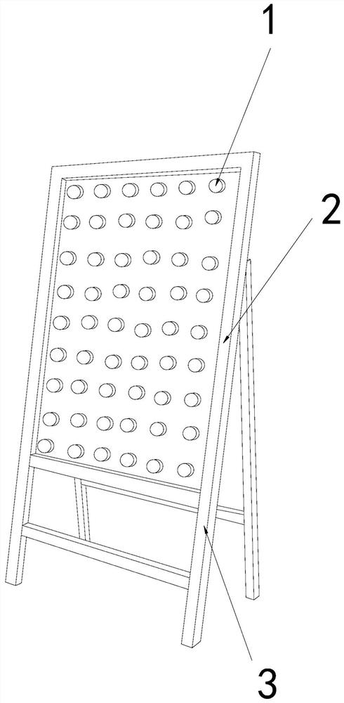
[0026] For example figure 1 -example Figure 5 Shown:

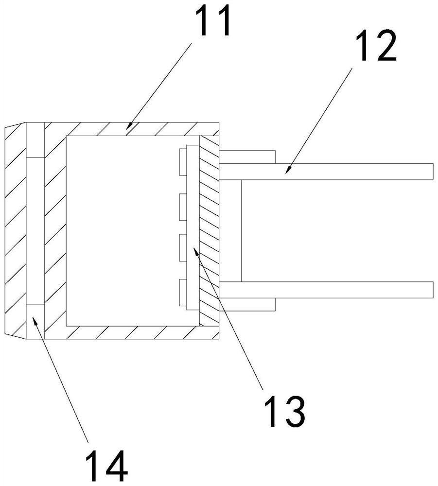
[0027] The invention provides a light-emitting diode lamp, the structure of which includes a lamp bead 1, a lamp board 2, and a support frame 3, the lamp board 2 and the support frame 3 are an integrated structure, and the lamp bead 1 and the lamp board 2 are embedded and connected The lamp bead 1 includes a shell 11, a pole 12, a wick 13, and an oil cleaning mechanism 14, the pole 12 is embedded in the right side of the wick 13, and the wick 13 is installed at the right end of the shell 11, The oil cleaning mechanism 14 is integrated with the housing 11 .

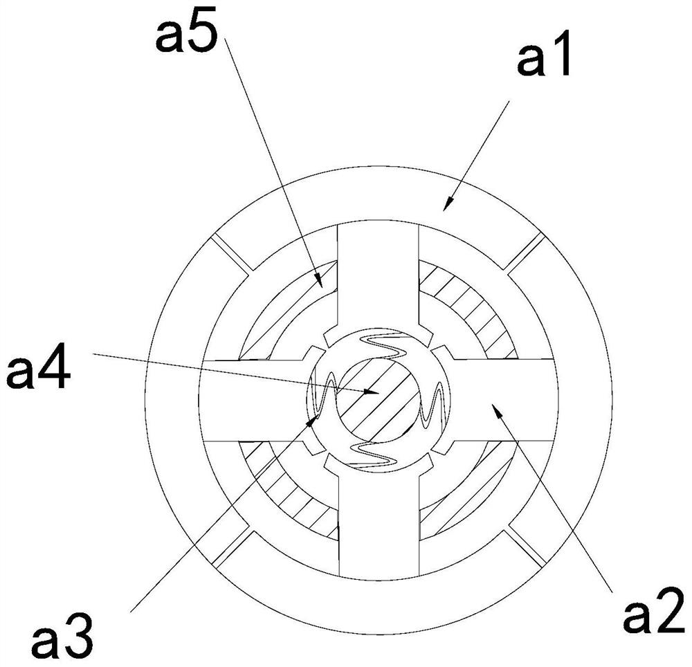
[0028] Wherein, the oil cleaning mechanism 14 includes an outer expansion ring a1, a booster rod a2, an elastic strip a3, a middle solid block a4, and an inner connection ring a5, and the outer side of the booster rod a2 is connected with the inner side of the outer expansion ring a1, And the booster rod a2 is in clearance fit with the inner ring a5, the elastic ba...

Embodiment 2

[0034] For example Figure 6 -example Figure 8 Shown:

[0035] Wherein, the lower slider b3 includes a flow-increasing groove b31, a baffle b32, and a bottom plate b33. connected, the flow-increasing groove b31 is in the form of a triangular groove structure, through which the flow-increasing groove b31 can enhance the downflow speed of the melted grease.

[0036] Wherein, the flow increasing tank b31 includes an external plate c1, a bottom plate c2, a sleeve frame c3, and a joint block c4, the external plate c1 is hinged to the right end of the joint block c4, and the sleeve frame c3 is connected to the bottom The middle part of the inner side of the plate c2 is embedded and connected, and the joint block c4 is movably engaged with the sleeve frame c3. Mercury liquid is installed between the rear end of the joint block c4 and the sleeve frame c3, and the temperature of the object is continuously increased, which can The mercury liquid between the combination block c4 and ...


PUM


Abstract

The invention discloses a light emitting diode lamp which structurally comprises a lamp bead, a lamp panel and a supporting frame, the lamp panel and the supporting frame are of an integrated structure, the lamp bead is fixedly connected with the lamp panel in an embedded mode, and a boosting rod can slide outwards along an inner connecting ring through pushing force generated by an elastic stripon the boosting rod. The boosting rod can push a bearing ring on an external expansion ring outwards to expand outwards, so that grease flowing downwards along the outer surface of the shell can flowinto a through groove, the grease is guided downwards into an external discharge cavity through the through groove in the arc-shaped inner wall, and through the continuously-increased heat generated by the lamp lead which is lightened for a long time, the mercury liquid between the combination block and the sleeve frame can be heated to expand, so that the expanded mercury can push the combinationblock to slide forwards along the sleeve frame, the external plate can swing downwards under the influence of the gravity of the external plate, and grease on the lower sliding block can be quickly and completely discharged.

Description

technical field [0001] The invention relates to the field of diode equipment, in particular to a light emitting diode lamp. Background technique [0002] LED lamp boards are usually used in night markets and shopping malls and other areas where billboards are required. The designated patterns or characters can be pieced together by the LED lamp beads that are lit according to the settings. It is a common device in life. Based on the above description, the present invention It is found that the existing light-emitting diode lamps mainly have the following deficiencies, such as: [0003] Due to the heavy oil fumes from the barbecue stand, grease will adhere to the LED lamp board placed next to the grill, and the LED lamp beads will generate heat when they are lit for a long time, so that the attached grease on the lamp beads will be heated and melted. Concentrated downward flow, long-term accumulation will cause a large amount of grease to concentrate at the lower end of the ...

Claims


Application Information

Patent Timeline
Patent Type & Authority Applications(China)
IPC IPC(8): G09F13/22
CPCG09F13/22G09F2013/222
Inventor 刘义
Owner 北京如利本辉科技有限公司
Why Eureka
Try Eureka