
Calibration plate and calibration method

A calibration method and calibration board technology, applied in image analysis, instruments, calculations, etc., can solve the problems of increasing the production cost of calibration boards, and achieve the effects of avoiding data errors in reading two-dimensional codes, saving costs, and ensuring accuracy

Pending Publication Date: 2021-01-05
HANGZHOU HIKROBOT TECH CO LTD
View PDF0 Cites 6 Cited by
  • Summary
  • Abstract
  • Description
  • Claims
  • Application Information

AI Technical Summary

Problems solved by technology

However, when making this kind of calibration board, it is necessary to use two-dimensional code generation software, thereby increasing the production cost of the calibration board

Method used


Image

  • Calibration plate and calibration method
  • Calibration plate and calibration method
  • Calibration plate and calibration method

Examples


Embodiment Construction

[0073] In order to make the purpose, technical solution and advantages of the present invention more clear, the present invention will be further described in detail below with reference to the accompanying drawings and examples.

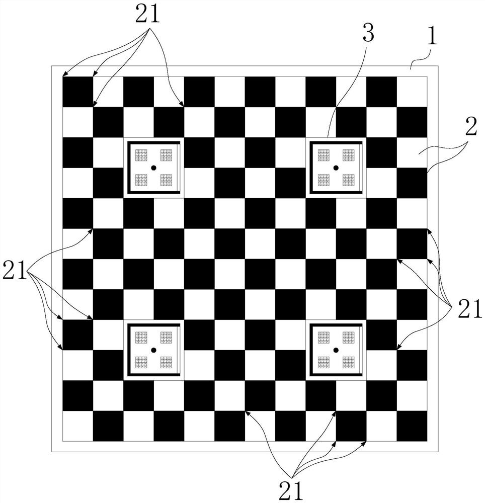
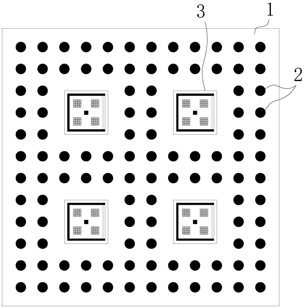
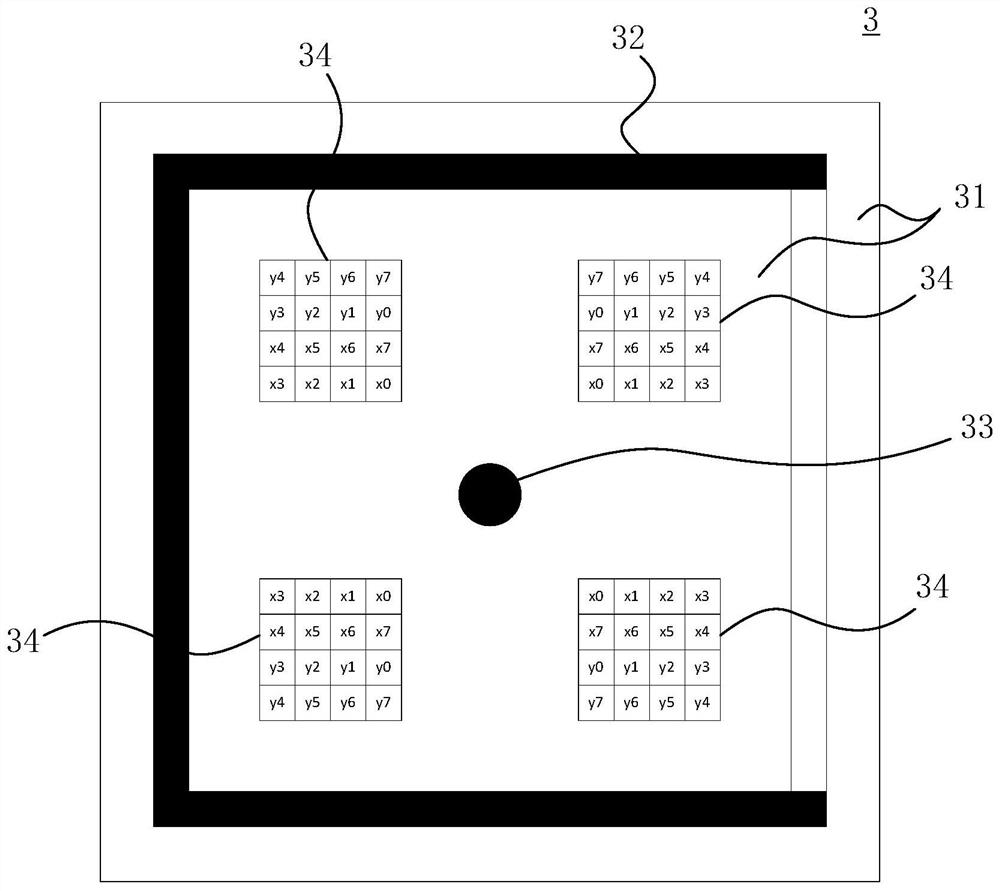
[0074] figure 1 A schematic diagram of an embodiment of the calibration plate of the present invention is shown, figure 2 A schematic diagram showing another embodiment of the calibration plate of the present invention, image 3 A specific embodiment of the positioning reference graphic unit in the calibration plate of the present invention is shown, Figure 4 Another specific embodiment of the positioning reference graphic unit in the calibration plate of the present invention is shown, wherein, image 3 The positioning datum graphic unit shown is figure 1 The positioning reference graphics unit used in , Figure 4 The positioning datum graphic unit shown is figure 2 The positioning reference graphics unit used in .

[0075] Such as figure...


PUM


Abstract

The invention discloses a calibration plate and a calibration method using the calibration plate. The calibration plate comprises: a substrate; a feature pattern which is printed on the surface of thesubstrate and is provided with a plurality of feature points; a positioning reference pattern unit printed on the substrate and surrounded by the feature pattern, wherein the positioning reference pattern unit comprises a static area; a orientation frame which is embedded in the static area; a central block which is positioned in the center of the inner region of the orientation frame and is positioned at any feature point in the feature pattern; and a coding matrix which is positioned in the internal region of the orientation frame and records the set coordinates of the central block. According to the calibration board and the calibration method, the positioning reference graphic unit containing the direction information and the index coordinate information is embedded into the characteristic pattern of the calibration board, the calibration board adopting a two-dimensional code for calibration is replaced, and the cost required by adopting two-dimensional code generation software issaved.

Description

technical field [0001] The invention relates to the technical field of machine vision, in particular to a calibration board and a calibration method. Background technique [0002] In the image measurement process and machine vision applications, in order to determine the relationship between the three-dimensional geometric position of a point on the surface of a space object and its corresponding point in the image, it is necessary to establish a geometric model of camera imaging, and these geometric model parameters are camera parameters. Under most conditions, these parameters must be obtained through experiments and calculations, and the process of solving these parameters is called camera calibration (or camera calibration). Whether it is in image measurement or machine vision applications, the calibration of camera parameters is a very critical link. The accuracy of calibration results and the stability of algorithms directly affect the accuracy of camera work results. ...

Claims


Application Information

Patent Timeline
IPC IPC(8): G06T7/80
CPCG06T7/80
Inventor 邓志辉王毅周杨
Owner HANGZHOU HIKROBOT TECH CO LTD
Learn More