
Display device and electronic equipment

A display device and display panel technology, which is applied in the direction of identification devices, static indicators, instruments, etc., can solve the problems of uneven display of the display panel, difference in resistance value of multiple fan-shaped traces, etc.

Active Publication Date: 2021-01-08
TCL CHINA STAR OPTOELECTRONICS TECH CO LTD
View PDF8 Cites 14 Cited by
  • Summary
  • Abstract
  • Description
  • Claims
  • Application Information

AI Technical Summary

Problems solved by technology

[0003] The present application provides a display device and electronic equipment to solve the technical problem of uneven display on the display panel due to the difference in the resistance values ​​of multiple fan-shaped traces in the prior art

Method used


Image

  • Display device and electronic equipment
  • Display device and electronic equipment
  • Display device and electronic equipment

Examples


Embodiment Construction

[0028] The following will clearly and completely describe the technical solutions in the embodiments of the application with reference to the drawings in the embodiments of the application. Apparently, the described embodiments are only some of the embodiments of the application, not all of them. Based on the embodiments in this application, all other embodiments obtained by those skilled in the art without making creative efforts belong to the scope of protection of this application.

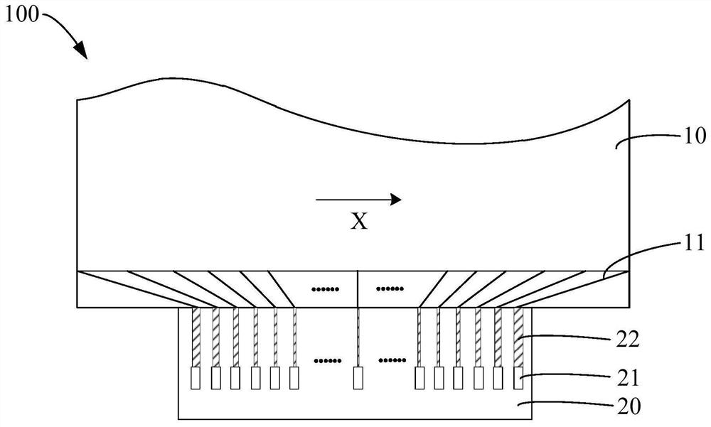
[0029] see figure 1 , figure 1 is the first structural schematic diagram of the display device provided in this application.

[0030] Such as figure 1 As shown, the display device 100 provided by the present application includes: a display panel 10, the display panel 10 includes a plurality of fan-shaped wires 11; and a source driver chip 20, in which a plurality of signal output terminals 21 and a plurality of Compensation line 22. The compensation wire 22 is used to reduce the difference ...


PUM


Abstract

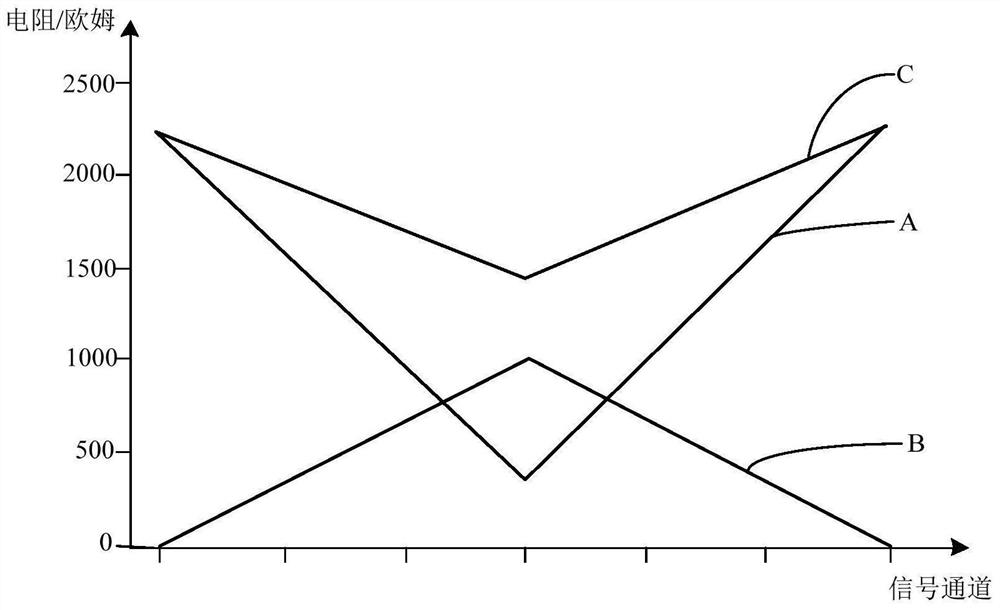
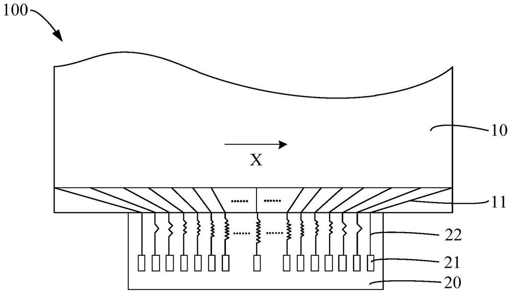
The invention provides a display device and electronic equipment, and the display device comprises a display panel which comprises a plurality of fan-shaped wires; and a source electrode driving chip,wherein a plurality of signal output ends and a plurality of compensation wires are arranged in the source electrode driving chip, the compensation wires are used for reducing the resistance difference among the fan-shaped wires, and the fan-shaped wires, the signal output ends and the compensation wires are in one-to-one correspondence. Each signal output end is electrically connected with one corresponding fan-shaped wire through one corresponding compensation wire. According to the invention, the compensation wires are arranged in the internal space of the source electrode driving chip, sothat the resistance difference among the fan-shaped wires is reduced, and the display uniformity of the display panel is improved.

Description

technical field [0001] The present application relates to the field of display technology, in particular to a display device and electronic equipment. Background technique [0002] In a display panel, in order to realize different display images, the source driver chip usually provides data voltages for displaying different images to the data lines. When the resolution of the display panel is high (that is, the number of data line columns of the display panel is large), the area of ​​the display area controlled by the same source driver chip increases, which will cause a fan-shaped area connected to the source driver chip (the fan-shaped area is Refers to the wiring area between the data line and the source driver chip. Because the shape of the entire wiring area is similar to a fan, it is called a fan-shaped area) The fan-shaped wiring in the area presents a structure of different lengths, that is, multiple fan-shaped Differences in the resistance values ​​of the wires lea...

Claims


Application Information

Patent Timeline
Patent Type & Authority Applications(China)
IPC IPC(8): G09F9/30G09G3/20
CPCG09F9/30G09G3/20H01L27/124
Inventor 刘金风
Owner TCL CHINA STAR OPTOELECTRONICS TECH CO LTD
Learn More