Mechanical linkage device applied to jewelry

A linkage device and jewelry technology, applied in applications, jewelry, clothing, etc., can solve the problems of inconvenient cleaning of jewelry, aesthetic fatigue, and inability for consumers to replace frequently, and achieve simple appearance adjustment methods, multiple changes in shape, and avoid aesthetic fatigue Effect

Active Publication Date: 2021-01-26
蔡文亮
View PDF7 Cites 0 Cited by
  • Summary
  • Abstract
  • Description
  • Claims
  • Application Information

AI Technical Summary

Problems solved by technology

[0002] With the development of society and economy, people's living standards have been greatly improved, and the jewelry industry has sprung up like mushrooms. The demand for jewelry is huge, which has driven the national economy. It can be predicted that with the further development of the economy , the jewelry industry will become bigger and bigger, and the styles of jewelry will become more and more diverse. However, most of the existing jewelry has a static structure and a single style, that is, the various components of the jewelry are usually fixed when they leave the factory. In the hands of consumers, consumers wear it to present a static aesthetic feeling
Over time, there will be a kind of aesthetic fatigue, and jewelry is a luxury item, most consumers cannot change it frequently, and jewelry cleaning is not convenient

Method used


Image

  • Mechanical linkage device applied to jewelry
  • Mechanical linkage device applied to jewelry
  • Mechanical linkage device applied to jewelry

Examples


Embodiment Construction

[0024] The following will clearly and completely describe the technical solutions in the embodiments of the present invention with reference to the accompanying drawings in the embodiments of the present invention. Obviously, the described embodiments are only some, not all, embodiments of the present invention.

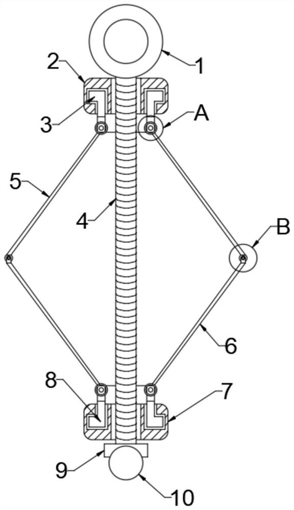
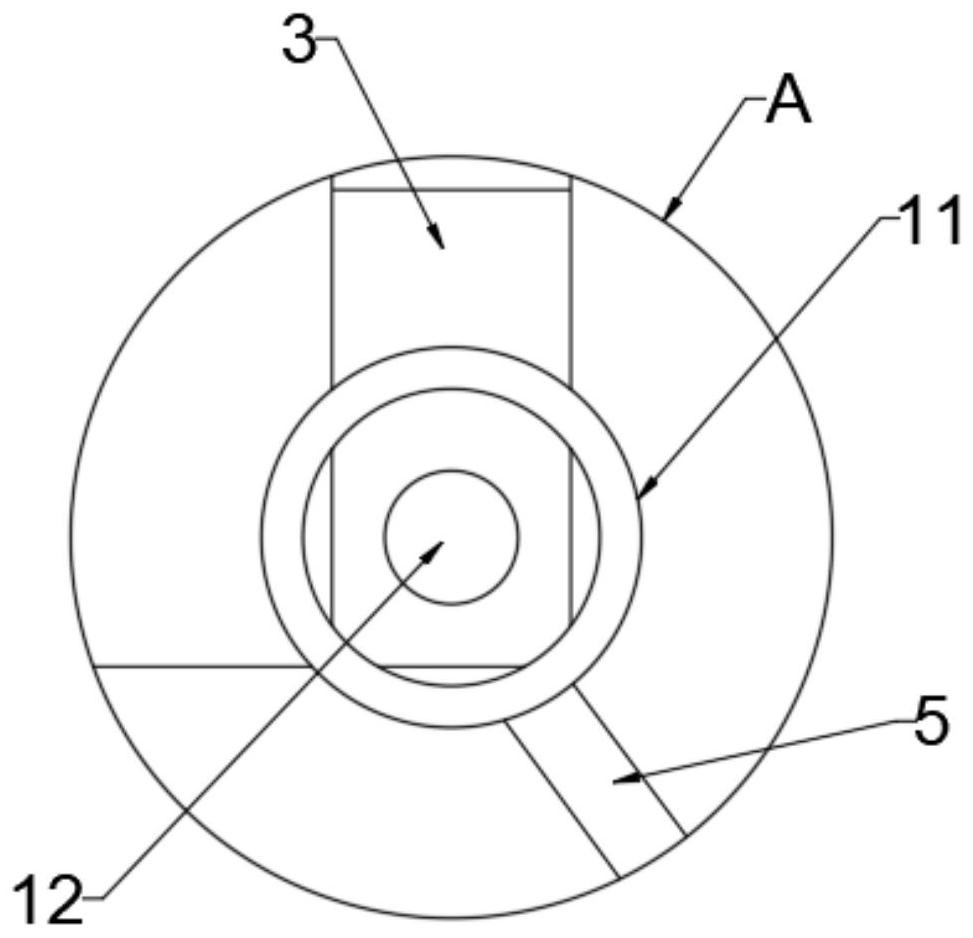
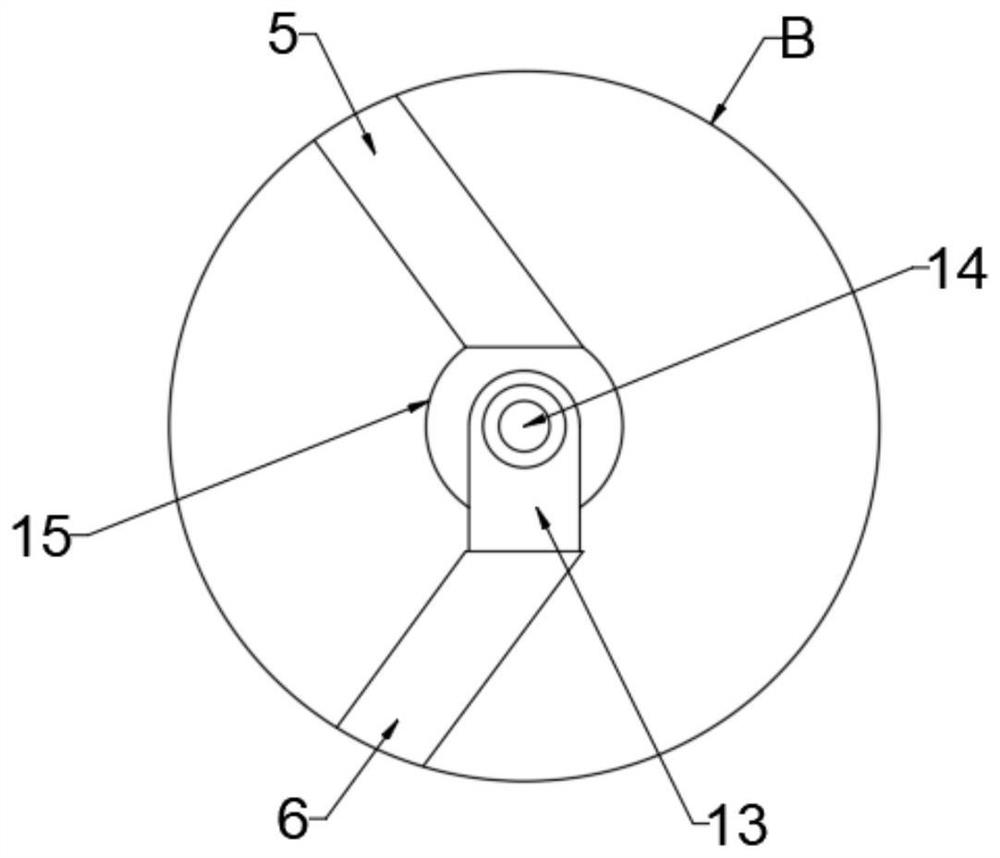
[0025] refer to Figure 1-Figure 5 , a mechanical linkage device applied to jewellery, comprising a fixed ring 1, the bottom of the fixed ring 1 is fixedly connected with a connecting rod 4, and the top outer wall and the bottom outer wall of the connecting rod 4 are screwed into the upper nut 2 and the lower nut respectively 7. The upper nut 2 is rotatably connected with a rotating part a3, the upper nut 2 is provided with a rotating groove a corresponding to the rotating part a3, the bottom of the rotating part a3 is rotatably connected with a plurality of decorative pieces a5, and the lower nut 7 is rotatably connected with a The rotating part b8, the top of the r...


PUM


Abstract

The invention discloses a mechanical linkage device applied to jewelry, and belongs to the technical field of jewelry modeling, the mechanical linkage device comprises a fixing ring, the bottom of thefixing ring is fixedly connected with a connecting rod, the outer side wall of the top and the outer side wall of the bottom of the connecting rod are in threaded sleeve connection with an upper nutand a lower nut respectively, and the upper nut is rotatably connected with a rotating part a; the upper nut is provided with a rotating groove a corresponding to the rotating piece a, the bottom of the rotating piece a is rotationally connected with a plurality of decorative pieces a, the lower nut is rotationally connected with a rotating piece b, and the top of the rotating piece b is rotationally connected with a plurality of decorative pieces b. According to the invention, the inclination angles of the decorative pieces a and the decorative pieces b can be adjusted by rotating the upper nut and the lower nut as required in the wearing process of the jewelry, so that the included angle between the decorative pieces a and the decorative pieces b is adjusted, the shape of the jewelry isadjusted, the appearance of the jewelry is changed, and aesthetic fatigue caused by long-term wearing of consumers is avoided.

Description

technical field [0001] The invention relates to the technical field of jewelry modeling, and more specifically, relates to a mechanical linkage device applied to jewelry. Background technique [0002] With the development of society and economy, people's living standards have been greatly improved, and the jewelry industry has sprung up like mushrooms. The huge demand for jewelry has driven the national economy. It can be predicted that with the further development of the economy , the jewelry industry will become bigger and bigger, and the styles of jewelry will become more and more diverse. However, most of the existing jewelry has a static structure and a single style, that is, the various components of the jewelry are usually fixed when they leave the factory. In the hands of consumers, consumers wear it to present a static beauty. Over time, there will be a kind of aesthetic fatigue, and jewelry is a luxury item, most consumers cannot change it frequently, and jewelry ...

Claims


Application Information

Patent Timeline
Patent Type & Authority Applications(China)
IPC IPC(8): A44C25/00
CPCA44C25/00
Inventor 蔡文亮
Owner 蔡文亮
Why Eureka
Try Eureka