Ultrasonic meter

An ultrasonic and gauge technology, applied in the field of ultrasonic gauges, can solve problems such as unreliable measurement results, and achieve the effect of avoiding unreliability, wear or damage

Pending Publication Date: 2021-01-26
ZENNER INT
View PDF3 Cites 0 Cited by
  • Summary
  • Abstract
  • Description
  • Claims
  • Application Information

AI Technical Summary

Problems solved by technology

Here, too, the reflector unit is arranged in the flow, which leads to unreliable measurement results

Method used


Image

  • Ultrasonic meter
  • Ultrasonic meter
  • Ultrasonic meter

Examples


Embodiment Construction

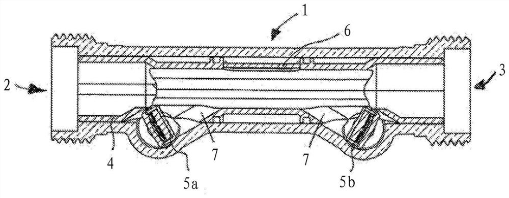
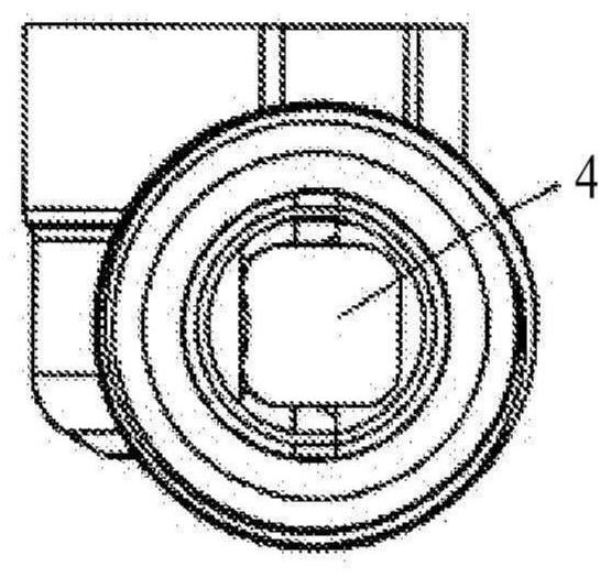
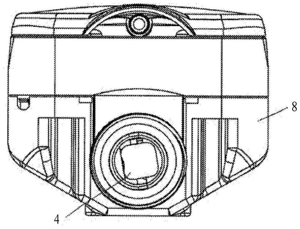
[0025] as by figure 1 It can be seen that the ultrasonic meter (1) according to the invention comprises a fluid inlet (2) and a fluid outlet (3) as well as a flow channel (4) connecting the fluid inlet (2) to the fluid outlet (3).

[0026] The flow channel (4) forms a measurement region which extends linearly in the direction of flow.

[0027] An ultrasonic transducer (5a, 5b) is installed sideways on the inlet and outlet of the flow channel (4) respectively, and the ultrasonic transducer sends the ultrasonic signal to the second The ultrasonic transducer (5b, 5a) or the ultrasonic signal is received by the second ultrasonic transducer.

[0028] The ultrasonic transducers ( 5 a , 5 b ) and reflectors are arranged in such a way that the fluid can flow undisturbed through the "open cross section", ie the flow is not affected by these elements. The reflector (6) is arranged on the inner wall of the flow channel (4).

[0029] With this arrangement, a direct flow on or around th...


PUM


Abstract

The invention relates to an ultrasonic meter (1) for detecting a flow amount or volume, comprising a fluid inlet (2), a fluid outlet (3) and a flow channel (4) arranged between the fluid inlet and thefluid outlet, as well as two ultrasonic transducers (5a, 5b) and at least one reflector (6) for ultrasonic signals. In order to provide an ultrasonic meter according to the above, in which there is apreferably undisturbed passage of fluid through the flow channel, in order to obtain a undistorted measurement result, according to the invention, the ultrasonic transducers are arranged outside theflow channel, wherein a respective inlet or outlet opening (7) for ultrasonic signals is provided between the ultrasonic transducers and the flow channel and running transverse to the longitudinal axis of the flow channel, and the reflector (6) is arranged on the wall of the flow channel opposite the inlet or outlet opening such that the ultrasonic signals of the ultrasonic transducers are reflected. With the attaching of the ultrasonic transducer outside of the flow channel and the arranging of the reflector in the region of the wall of the flow channel, it is achieved that the passage of fluid through the flow channel is not disturbed by these elements. In this way, a distortion of the measurement result is prevented.

Description

technical field [0001] The invention relates to an ultrasonic meter for detecting flow or flow volume, comprising a fluid inlet, a fluid outlet and a flow channel arranged between the fluid inlet and the fluid outlet, two ultrasonic transducers and at least one for ultrasonic signals reflector. Background technique [0002] EP1798528A1 is known as a flow measuring device for a fluid medium, said flow measuring device comprising: a housing, the interior of which is defined by the housing inner wall; a measuring tube arranged inside the housing, which is determined for A measuring line for runtime measurement; and an ultrasonic measuring device comprising at least one ultrasonic transducer for emitting ultrasonic waves into the interior of the housing; at least one turning mirror on the measuring line, which has a front side and On the rear side opposite the front side, the ultrasonic waves are deflected into the measurement line by means of a deflection mirror, wherein the d...

Claims


Application Information

Patent Timeline
Patent Type & Authority Applications(China)
IPC IPC(8): G01F1/66G01F15/14
CPCG01F1/662G01F15/006G01F15/14G01F1/667
Inventor 曼弗雷德·卡尔梅斯
Owner ZENNER INT
Why Eureka
Try Eureka