Wrist joint prosthesis

A wrist joint prosthesis and prosthesis technology, applied in the direction of wrist joints, ankle joints, joint implants, etc., can solve problems such as the inability to realize the circular movement function of the radiocarpal joint

Pending Publication Date: 2021-02-02
苏州微创感动赋能医疗科技有限公司
View PDF0 Cites 4 Cited by
  • Summary
  • Abstract
  • Description
  • Claims
  • Application Information

AI Technical Summary

Problems solved by technology

[0003] The object of the present invention is to provide a wrist joint prosthesis to solve the problem that the existing wrist joint prosthesis cannot realize the circular movement function of the radiocarpal joint

Method used


Image

  • Wrist joint prosthesis
  • Wrist joint prosthesis
  • Wrist joint prosthesis

Examples


Embodiment 1

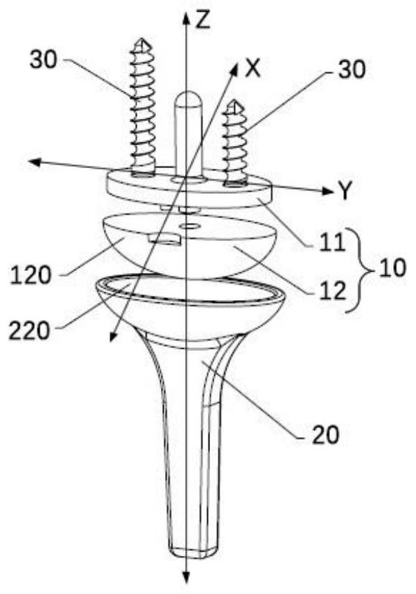
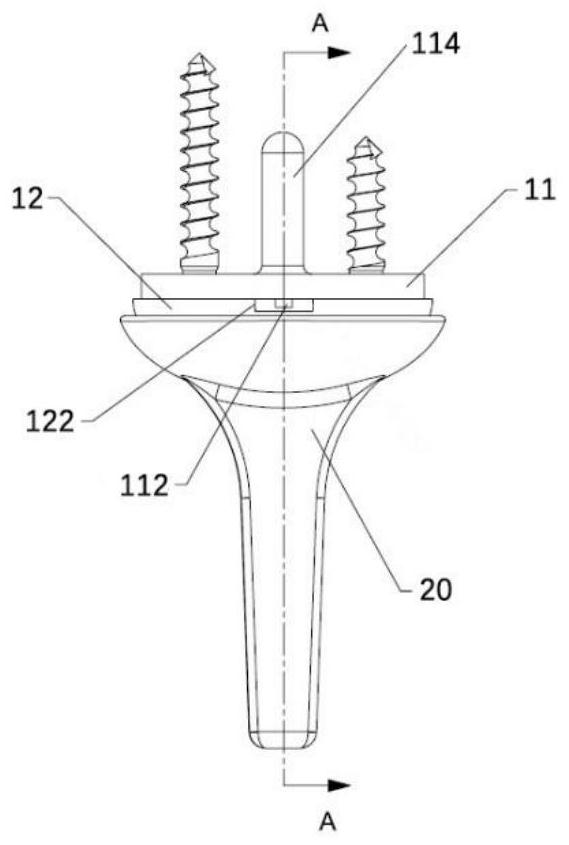
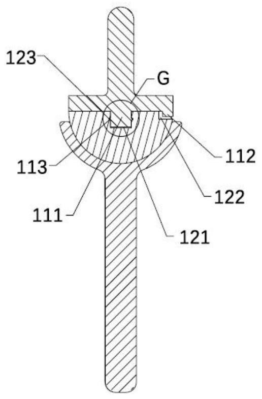
[0064]Please refer toFigure 1 to Figure 7 ,among them,figure 1 Is an exploded schematic diagram of the wrist joint prosthesis of the first embodiment of the present invention;figure 2 It is a schematic diagram of the assembly of the wrist joint prosthesis of the first embodiment of the present invention;image 3 Yesfigure 2 The cross-sectional schematic diagram of the wrist joint prosthesis shown along the line A-A;Figure 4 Yesimage 3 Enlarged view of central G;Figure 5 Is a schematic diagram of the carpal support of the first embodiment of the present invention;Image 6 Is a schematic diagram of the wrist bone connector of the first embodiment of the present invention;Figure 7 It is a schematic diagram of the radial prosthesis of the first embodiment of the present invention.

[0065]Such asfigure 1 As shown, the first embodiment of the present invention provides a wrist joint prosthesis, which includes: a carpal prosthesis 10 and a radial prosthesis 20; the carpal prosthesis 10 has a f...

Embodiment 2

[0079]Please refer toFigure 8 to Figure 13 ,among them,Figure 8 Is an exploded schematic diagram of the wrist joint prosthesis of the second embodiment of the present invention;Picture 9 Is a schematic diagram of the assembly of the wrist joint prosthesis of the second embodiment of the present invention;Picture 10 YesPicture 9 The cross-sectional schematic diagram of the wrist joint prosthesis shown along the line B-B;Picture 11 Is a schematic diagram of the carpal support of the second embodiment of the present invention;Picture 12 Is a schematic diagram of the wrist bone connector of the second embodiment of the present invention;Figure 13 It is a schematic diagram of the radial prosthesis of the second embodiment of the present invention.

[0080]The wrist joint prosthesis provided in the second embodiment of the present invention is basically the same as the wrist joint prosthesis provided in the first embodiment, and the same parts will not be described, and only the differences ...

Embodiment 3

[0085]Please refer toFigure 14 to Figure 19 ,among them,Figure 14 Is a schematic diagram of the assembly of the wrist joint prosthesis of the third embodiment of the present invention;Figure 15 YesFigure 14 The cross-sectional schematic diagram of the wrist joint prosthesis shown along the line C-C;Figure 16 Is a schematic diagram of the carpal support of the third embodiment of the present invention;Figure 17 Is a schematic diagram of the wrist bone connector of the third embodiment of the present invention;Figure 18 Is a schematic diagram of the radial prosthesis of the third embodiment of the present invention;Figure 19 It is a schematic diagram of another preferred example of a wrist prosthesis in the third embodiment of the present invention.

[0086]The wrist joint prosthesis provided in the third embodiment of the present invention is basically the same as the wrist joint prosthesis provided in the first embodiment, and the same parts are not described again, and only the differ...


PUM


Abstract

The invention provides a wrist joint prosthesis. The wrist joint prosthesis comprises a carpal prosthesis and a radius prosthesis, wherein the carpal prosthesis is provided with a first curved surface, the radius prosthesis is provided with a second curved surface matched with the first curved surface in shape, and the carpal prosthesis and the radius prosthesis are connected in an abutting mode in the first direction through the first curved surface and the second curved surface. The carpal prosthesis is configured to be rotatable relative to the radius prosthesis around a second direction and a third direction which are perpendicular to the first direction, and one end used for being connected with carpal, of the carpal prosthesis is rotatable relative to one end used for being connectedwith the radius, of the radius prosthesis around the first direction. According to the configuration, one end used for being connected with carpal, of the wrist joint prosthesis is configured to rotate around the first direction relative to one end used for being connected with the carpal, of the radius prosthesis, so that the wrist joint prosthesis can achieve the circling motion function of a radial wrist joint, the wrist joint mobility of a patient is improved, and the satisfaction degree of the patient is increased.

Description

Technical field[0001]The invention relates to the technical field of orthopedic tools, in particular to a wrist joint prosthesis.Background technique[0002]The wrist joint is one of the most flexible and important joints in the human body. For the treatment of traumatic, degenerative wrist arthritis, severely damaged rheumatoid arthritis and other diseases, most of the previous treatments have been wrist fusion. Mainly, with the development of medicine and technology and patients eagerly hope to be able to solve pain while retaining the mobility of their wrist joints, total wrist joint replacement surgery is increasingly used in wrist joint treatment. At present, wrist prosthesis has developed to a non-restrictive full wrist prosthesis, which can achieve palm flexion, dorsal extension, ulnar deviation, and radial deviation. However, the current wrist prosthesis cannot achieve the radial carpal joint rotation. Movement function.Summary of the invention[0003]The purpose of the present ...

Claims


Application Information

Patent Timeline
Patent Type & Authority Applications(China)
IPC IPC(8): A61F2/42A61F2/46
CPCA61F2/4261A61F2/4606A61F2002/4264A61F2002/4271
Inventor 孙延东周思远黄有军
Owner 苏州微创感动赋能医疗科技有限公司
Why Eureka
Try Eureka