Vehicle timing method, timing sensor, receiver, client and timing system
A sensor and receiver technology, applied in the field of competition timing, can solve problems such as inaccurate timing
- Summary
- Abstract
- Description
- Claims
- Application Information
AI Technical Summary
Problems solved by technology
Method used
Image
Examples
Embodiment 1
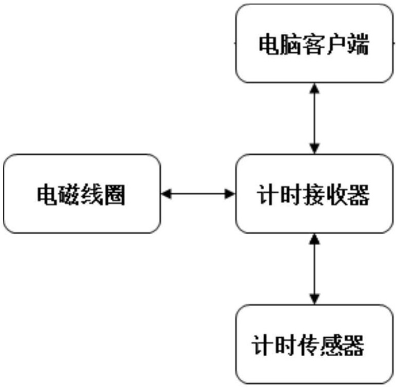
[0048] figure 1 It is a schematic diagram of the application scene of the vehicle timing method in Embodiment 1 of the present invention. Such as figure 1 As shown, the application scenario of the timing method in Embodiment 1 of the present invention includes an electromagnetic coil, a timing sensor, a timing receiver and a client, wherein the electromagnetic coil is a closed coil composed of insulated wires, laid at the start and stop line of the track, and the timing receiver It is connected with the electromagnetic coil and continuously generates a square wave pulse signal of a specific frequency, thereby forming an alternating magnetic field near the electromagnetic coil. The timing sensor is flat and fixed under the chassis of the vehicle. In Embodiment 1 of the present invention, the vehicle is a go-kart. The timing receiver is connected with the client through a communication cable (such as RS485). Exemplarily, in Embodiment 1 of the present invention, the client ma...
Embodiment 2
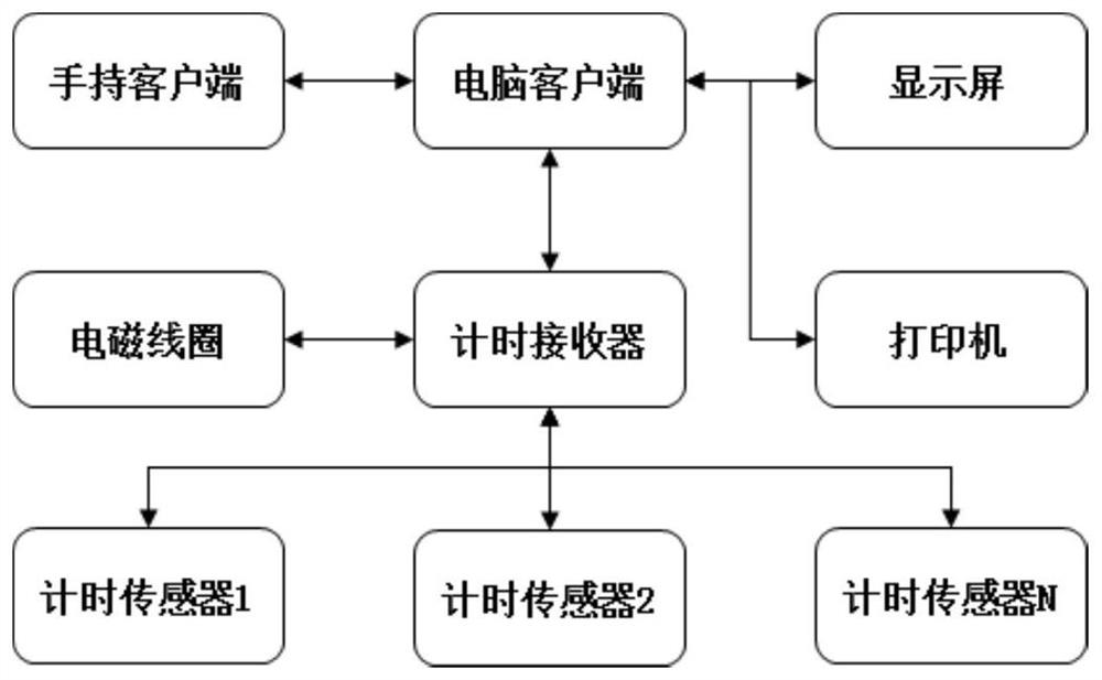
[0061] image 3 It is a schematic diagram of an application scenario of the timing method in Embodiment 2 of the present invention. Such as image 3 As shown, the application scenarios of the timing method in Embodiment 2 of the present invention include electromagnetic coils, N timing sensors, timing receivers, computer clients, handheld clients, display screens and printers. The electromagnetic coil is a closed coil composed of insulated wires, which is laid at the start and end line of the track. The timing receiver is connected to the electromagnetic coil and continuously generates a square wave pulse signal of a specific frequency, thereby forming an alternating magnetic field near the electromagnetic coil. The timing sensor is flat and fixed on the bottom of the kart chassis. One timing sensor is fixed under the chassis of one kart, which is applicable to the timing of N karts in Embodiment 2 of the present invention. The timing receiver is connected with the computer ...
Embodiment 3
[0080] Embodiment 3 of the present invention provides a timing system, which includes a timing sensor, a timing receiver, and a client.
[0081] In Embodiment 3 of the present invention, the timing sensor is flat and fixed under the chassis of the go-kart. The timing receiver is connected to the electromagnetic coil and continuously generates a square wave pulse signal of a specific frequency, thereby forming an alternating magnetic field near the electromagnetic coil. The electromagnetic coil is a closed coil composed of insulated wires, which is laid at the start and stop line of the track, and the timing receiver is connected to the client through a communication cable (such as RS485).
[0082] Figure 5 It is a structural schematic diagram of the timing sensor in Embodiment 3 of the present invention, as Figure 5 As shown, the timing sensor according to Embodiment 3 of the present invention includes a sensing module 50 , a first processing module 52 and a first sending m...
PUM
 Abstract
Description
Claims
Application Information
 - R&D
- Intellectual Property
- Life Sciences
- Materials
- Tech Scout
- Unparalleled Data Quality
- Higher Quality Content
- 60% Fewer Hallucinations
Browse by: Latest US Patents, China's latest patents, Technical Efficacy Thesaurus, Application Domain, Technology Topic, Popular Technical Reports.
© 2025 PatSnap. All rights reserved.Legal|Privacy policy|Modern Slavery Act Transparency Statement|Sitemap|About US| Contact US: help@patsnap.com


