Ka-waveband dual-circular polarization switchable transceiving antenna

A technology of dual circular polarization, transmitting and receiving antennas, which is applied in the directions of antenna coupling, antenna grounding device, antenna grounding switch structure connection, etc., which can solve the problems of increased mutual coupling effect, array performance impact, and maintenance, etc., to reduce Active standing wave, small gain loss, and increased isolation

Active Publication Date: 2021-02-05
重庆两江卫星移动通信有限公司
View PDF11 Cites 2 Cited by
  • Summary
  • Abstract
  • Description
  • Claims
  • Application Information

AI Technical Summary

Problems solved by technology

[0003] In the theory of array antennas, array elements are limited by the scan angle and element spacing, so the element size must be less than half of the wavelength corresponding to the highest frequency of the operating frequency band; the radiation pattern of the antenna element in a wide operating frequency band must be remain the same or change very little, which also increases the difficulty of miniaturization design for miniaturized broadband antennas
When working in the low frequency band, the mutual coupling effect between the array elements will increase rapidly after the unit spacing (electrical size) is reduced, so that the radiation performance of the array does not meet expectations, especially in the case of large-angle scanning, the mutual coupling effect will affect the The performance of the array will have a great impact and even make the array unable to work normally, so improving the mutual coupling environment between the antenna elements of the broadband phased array is the key to ensure its normal operation in the wide bandwidth angular scanning state

Method used


Image

  • Ka-waveband dual-circular polarization switchable transceiving antenna
  • Ka-waveband dual-circular polarization switchable transceiving antenna

Examples


Embodiment

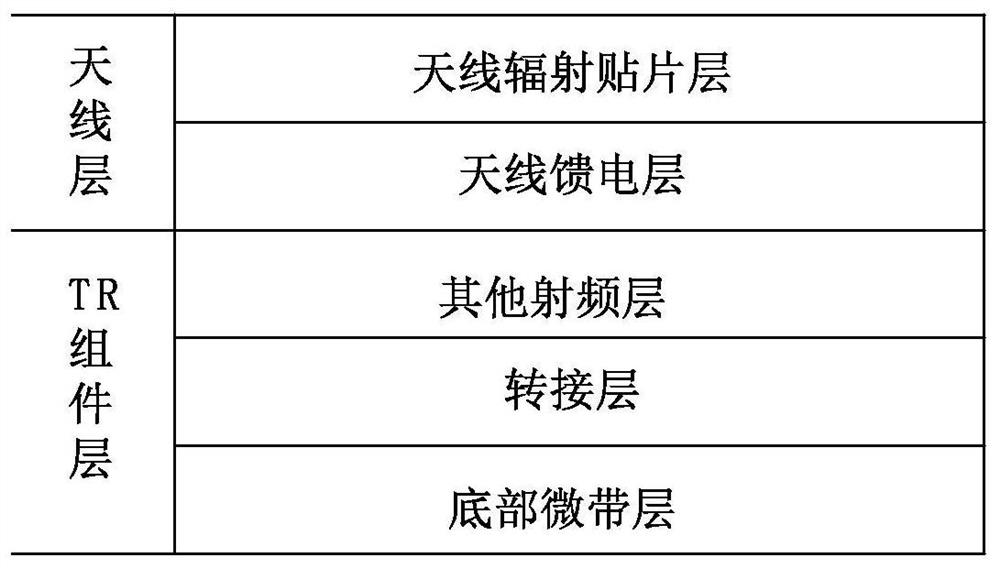
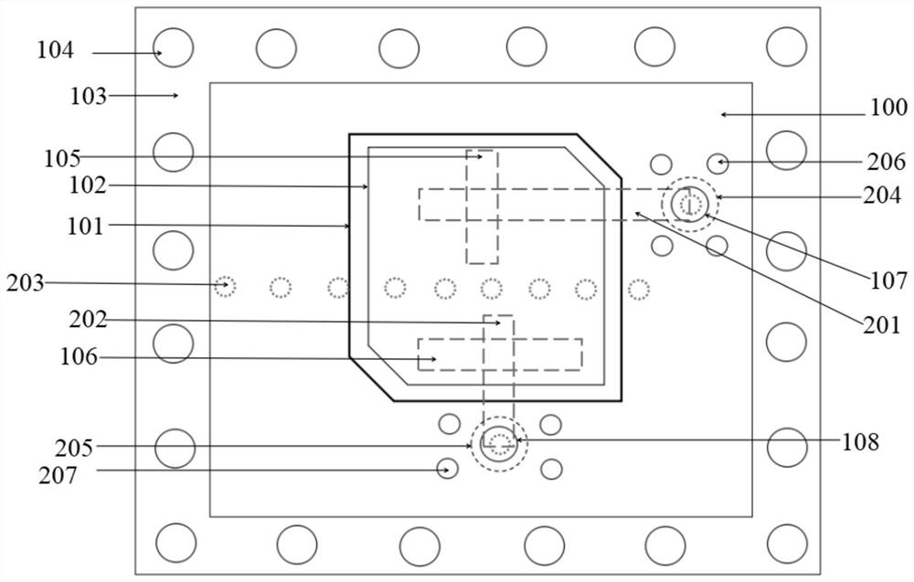
[0027] like figure 1 and figure 2 As shown, a ka-band dual circularly polarized switchable transceiver antenna of the present invention includes an antenna radiation patch layer, an antenna feed layer, a TR component layer, and probes interspersed between layers arranged sequentially from top to bottom;

[0028] The antenna radiation patch layer includes an antenna radiation patch medium layer 100, the upper surface of the antenna radiation patch medium layer is provided with a radiation patch 101, and the lower surface is provided with a radiation metal formation, and the antenna radiation patch medium layer is sandwiched by a The main radiating patch 102 has two H-shaped coupling slots 105 and 106 on the radiating metal formation, which are respectively the feeding positions for right-handed circular polarization and left-handed circular polarization. Metal strip frames 103 and metal Metallized via hole 104, wherein the metallized via hole connects the radiation metal form...


PUM


Abstract

The invention discloses a ka-waveband dual-circular polarization switchable transceiving antenna which comprises an antenna radiation patch layer, an antenna feed layer, a TR assembly layer and probes. The antenna radiation patch layer comprises an antenna radiation patch dielectric layer, a slave radiation patch is arranged on the upper surface of the antenna radiation patch dielectric layer, a radiation metal ground layer is arranged on the lower surface of the antenna radiation patch dielectric layer, a main radiation patch is clamped in the middle of the antenna radiation patch dielectriclayer, and a coupling gap is formed in the radiation metal ground layer; the antenna feed layer comprises an antenna feed dielectric layer arranged under the radiation metal ground layer, a feed metalground layer is arranged on the lower surface of the antenna feed dielectric layer, and two T-shaped strip line feed structures are arranged in the antenna feed dielectric layer; the TR assembly layer comprises other radio frequency layers, a switching layer and a bottom microstrip layer. The probes comprise a first probe and a second probe. The phased array multilayer microwave plate dual circularly polarized antenna is formed by arranging the antenna radiation patch layer, the antenna feed layer and the TR assembly layer, and has the characteristics of broadband and wide beam.

Description

technical field [0001] The invention relates to the field of ka-band phased array antennas, in particular to a ka-band dual circular polarization switchable transceiver antenna. Background technique [0002] At present, millimeter-wave active phased array transceiver components are moving toward increasingly miniaturized designs. In order to improve space utilization, radio frequency signals must be transmitted upwards between multi-layer microwave substrates. As the frequency increases, the microwave transmission line and propagation performance will become more and more complex. In the multilayer board, other layers, such as the circuit layer, control layer, etc., are easy to interfere with the feed point structure of the antenna layer, especially the dual The polarization structure doubles the difficulty. At this time, the two polarized feeders must be separated through the transfer layer to reach the chip layer and be connected to it. [0003] In the theory of array ant...

Claims


Application Information

Patent Timeline
Patent Type & Authority Applications(China)
IPC IPC(8): H01Q1/38H01Q1/48H01Q1/50H01Q1/52
CPCH01Q1/52H01Q1/38H01Q1/50H01Q1/48Y02D30/70
Inventor 王建伟曾令昕罗袁君邹景孝胡侯平刘大桥
Owner 重庆两江卫星移动通信有限公司
Why Eureka
Try Eureka