Medium and low yield field soil condition improvement equipment and improvement method thereof

A medium and low-yield, soil technology, applied in the direction of soil lifting machinery, shovel, plow, etc., can solve the problems of feeding pipe jam, the effect of feeding speed of feeding pipe, and insufficient soil fertilization.

Inactive Publication Date: 2021-02-09
安徽军松现代农业科技有限公司
View PDF1 Cites 0 Cited by
  • Summary
  • Abstract
  • Description
  • Claims
  • Application Information

AI Technical Summary

Problems solved by technology

[0003] In view of the above situation, in order to overcome the defects of the prior art, the present invention provides a kind of equipment and method for improving the soil conditions of medium and low-yield fields, which effectively solves the problems in the current market when discharging st...

Method used


Image

  • Medium and low yield field soil condition improvement equipment and improvement method thereof
  • Medium and low yield field soil condition improvement equipment and improvement method thereof
  • Medium and low yield field soil condition improvement equipment and improvement method thereof

Examples


Embodiment 1

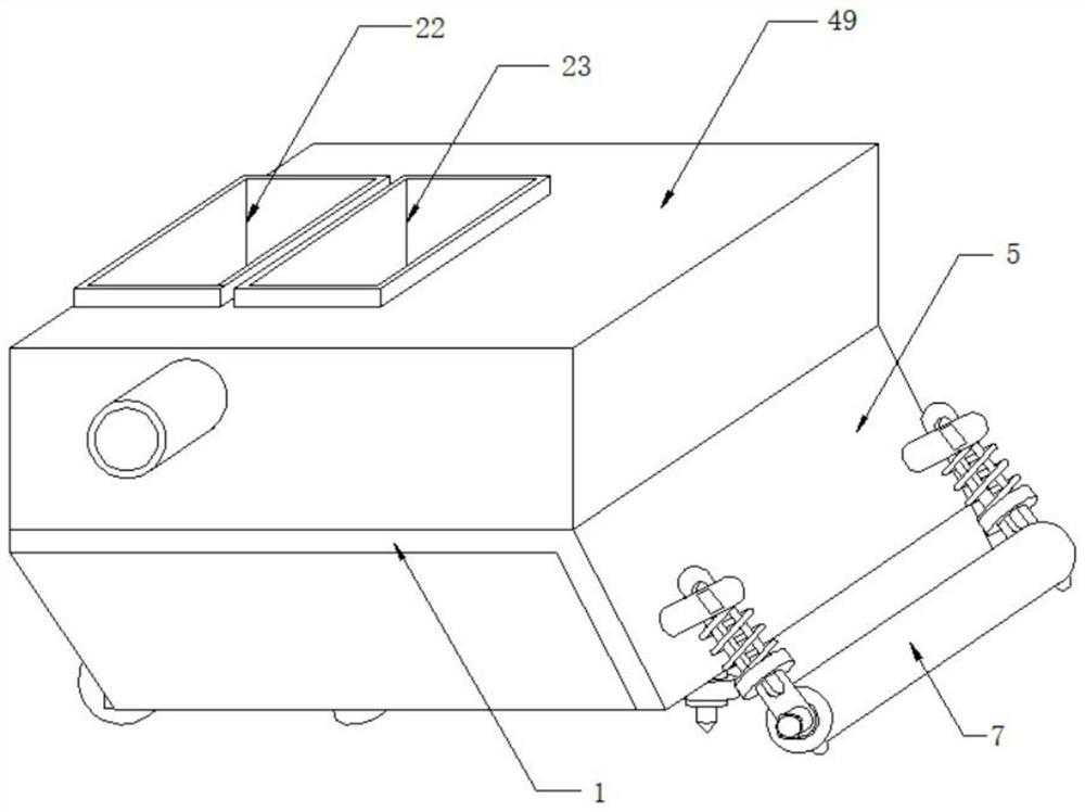
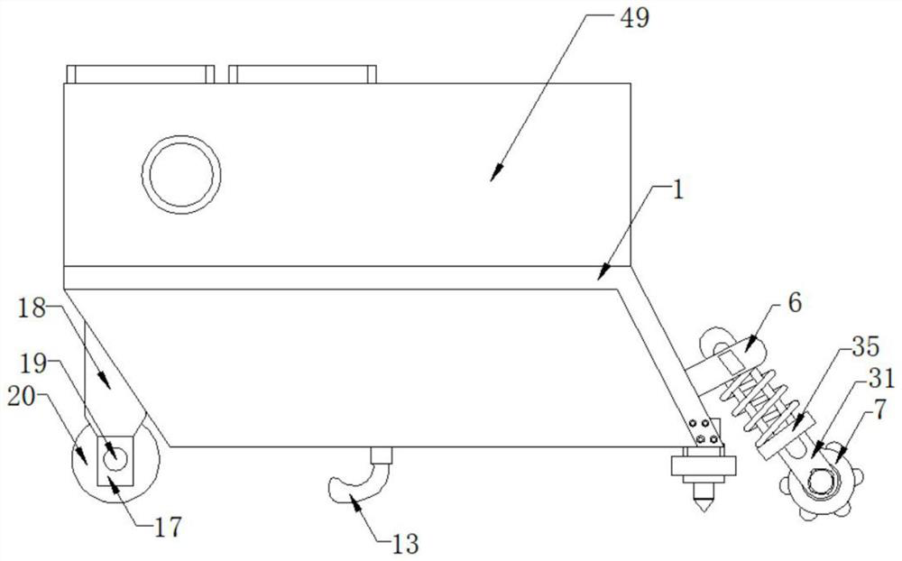
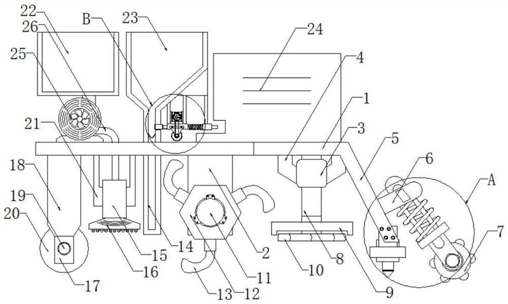
[0035] Embodiment one, by Figure 1-8 Given, the present invention includes a drag support plate 1, the bottom of the drag support plate 1 is fixedly installed with a first rotating bracket 18, the bottom of the first rotating bracket 18 is fixedly equipped with a concave bracket 17, and the inside of the concave bracket 17 is provided with a spiral cutter head 20. Two rotating bearings 19 are fixedly installed inside the concave bracket 17, both ends of the spiral cutter head 20 are rotatably socketed with the concave bracket 17 through the rotating bearings 19, and two second rotating bearings are fixedly installed on the bottom of the drag support plate 1. Bracket 2, the two second rotating brackets 2 are distributed symmetrically around the axis of the drag support plate 1, the inner rotation of the two second rotating brackets 2 is sleeved with a transmission link 11, and the outer fixed sleeve of the transmission link 11 is There are several hexagonal cutterheads 12, and...

Embodiment 2

[0036] Embodiment 2. On the basis of Embodiment 1, a switch panel is fixedly installed on one side of the protective shell 49, and a water pump switch, a transmission switch and an atomization switch are arranged on one side of the switch panel. The transmission motor 39 is electrically connected to the power supply through the transmission switch, and the liquefaction sprayer 15 is electrically connected to the power supply through the atomization switch.

Embodiment 3

[0037] Embodiment 3, on the basis of Embodiment 1, the outer parts of the three transfer rods 8 are fixedly sleeved with soil-shielding circular plates 9, and the three crushing cutter heads 10 are respectively set with the corresponding soil-shielding circular plates 9 Next, the depth value of each pulverizing cutter head 10 is greater than the depth value of the soil shielding circular plate 9 .


PUM


Abstract

The invention relates to the technical field of agricultural equipment, discloses medium and low yield field soil condition improvement equipment and an improvement method thereof, and solves the problems that when stored materials and internal waste materials are discharged in the current market, as a discharging pipeline is influenced by the discharging speed, and the phenomenon of material blockage occurs in the discharging pipeline, discharging is not uniform enough, soil fertilization is not sufficient, and the soil improvement effect is affected. The equipment comprises a dragging supporting plate, a first rotating support is fixedly installed at the bottom of the dragging supporting plate, and a concave support is fixedly installed at the bottom of the first rotating support. According to the equipment, large soil blocks in a soil layer can be crushed; and the soil blocks in the soil are fully fertilized, a nutrient solution is uniformly sprayed to the soil blocks, so that the fertilizer required by the soil is uniformly scattered, the soil is subjected to saline-alkali-acid comprehensive treatment, and the soil with a higher soil turning gradient is flattened.

Description

technical field [0001] The invention belongs to the technical field of agricultural equipment, in particular to equipment for improving soil conditions in low- and medium-yield fields and an improving method thereof. Background technique [0002] According to the Chinese invention patent (Application No.: CN201820900864.2, application date: 2018.06.12) disclosed "a kind of tiller mechanism for soil improvement", its structure is "comprising the main body of the tiller, and the main body of the tiller A switch and a power cord are arranged on the surface of the left upper end, and the inside of the lower right side of the main body of the tiller is connected with a rotary tiller through bearings, and a bracket is provided on the left side of the main body of the tiller, and the right side of the bracket is The turntable is connected with the rotation of the motor, the lower side of the turntable is connected with the connecting rod through the first rotating shaft, the right ...

Claims


Application Information

Patent Timeline
IPC IPC(8): A01B49/02A01B49/06A01B77/00
CPCA01B49/022A01B49/025A01B49/065A01B77/00
Inventor 韩锐丰
Owner 安徽军松现代农业科技有限公司
Why Eureka
Try Eureka