A voltage and current quasi-fixed frequency control device and method

A technology of a control device and a voltage detection circuit, which is applied in control/regulation systems, output power conversion devices, electrical components, etc., can solve the problems of output capacitor equivalent series resistance affecting stability and wide switching frequency range.

Inactive Publication Date: 2021-04-23
SICHUAN UNIV
View PDF13 Cites 0 Cited by
  • Summary
  • Abstract
  • Description
  • Claims
  • Application Information

AI Technical Summary

Problems solved by technology

[0003] The purpose of the present invention is to provide a voltage and current quasi-fixed frequency control device and method, which are used to solve the problems of wide switching frequency variation range and output capacitor equivalent series resistance affecting its stability in the voltage-type pulse frequency modulation technology in the prior art. question

Method used


Image

  • A voltage and current quasi-fixed frequency control device and method
  • A voltage and current quasi-fixed frequency control device and method
  • A voltage and current quasi-fixed frequency control device and method

Examples


Embodiment 1

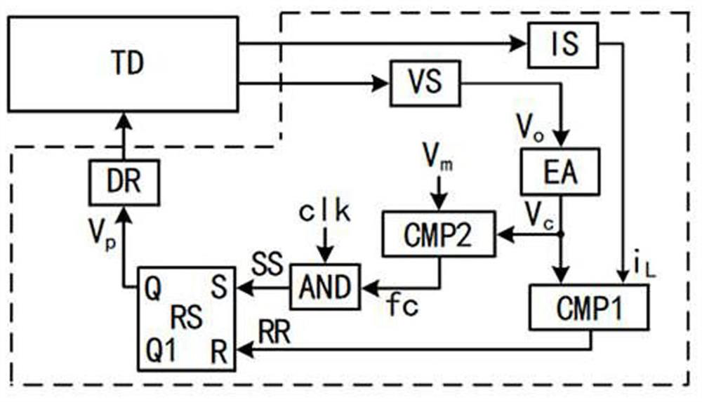
[0021]Joinfigure 1 As shown, a voltage, current is quasi-frequency control device, including a voltage detecting circuit VS, a current detecting circuit IS, an error amplifier EA, a first comparator CMP1, a second comparator CMP2, and an AND gate AND, a flip-flop RS, and a driving circuit. DR, voltage detecting circuit VS, current detecting circuit IS, and drive circuit DR respectively correspond to the voltage output of the converter Td, the current output terminal of the converter, the switch tube of the converter, the voltage detecting circuit VS and the error amplifier EA; current The detection circuit IS is connected to the input end of the first comparator CMP1; the output of the error amplifier EA is connected to the input of the first comparator CMP1, the input end of the second comparator CMP2; the preset error signal reference value VmConnect to the input end of the second comparator CMP2; the output terminal of the second comparator CMP2 and the clock signal CLK is connec...

Embodiment 2

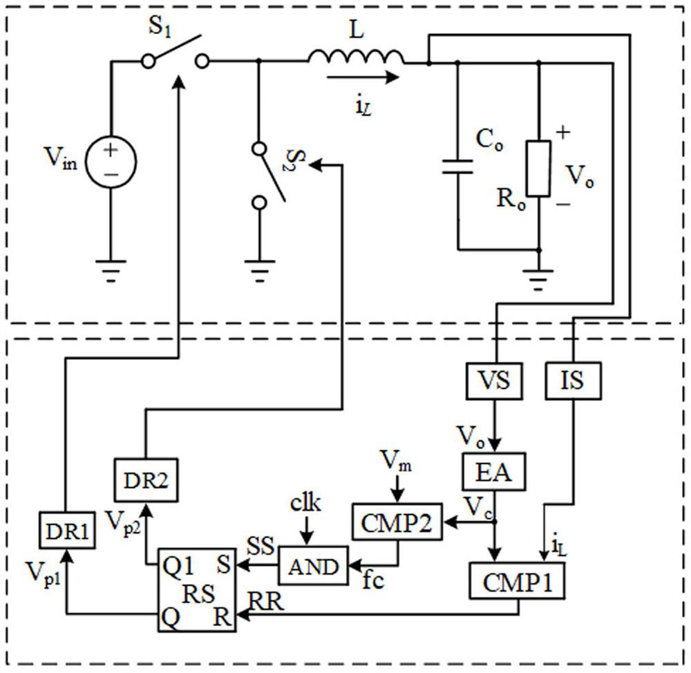
[0025]A voltage, current ratio fixed frequency control method, based on the above control device, the embodiment of the present invention replaces the converter TD in the above embodiment to a synchronous rectified BUCK converter, such asfigure 2 As shown, the control method is:

[0026]At any cycle start, the converter TD output voltage VoAnd inductor current IL, Output voltage VoWith the reference voltage VREF1 Generating voltage control signal via error amplifier EAcInductive current ILConnect to one input of the first comparator CMP1, with the voltage control signal VcAfter comparing the signal RR, the R-terminal input signal is used as the trigger RS; the preset error signal reference value VmVoltage control signal VcAt the same time, the input terminal of the second comparator CMP2 is connected, the preset error signal reference value VmVoltage control signal VcGenerate pulse selection signal f through comparisoncPulse selection signal fcConnect to the clock signal CLK to the gat...

Embodiment 3

[0035]Such asFigure 9 As shown, the embodiment of the present invention replaces the converter Td in the above embodiment to the BOOST converter. In the figure, Vin For the input voltage, L is the power inductor, S is the power switch tube, CoFor output capacitance, RoFor load resistance, VS is the output voltage detecting circuit, IS is inductively current detecting circuit, Vp1The pulse control signal of the switch tube S.

[0036]The present invention can also be used in a variety of circuit topologies such as BUCK-BOOST converters, a FlyBack converter, a Forward converter, suitable for switching converters of a variety of topologies.


PUM


Abstract

The invention discloses a voltage and current quasi-fixed frequency control device, comprising a voltage detection circuit, a current detection circuit, an error amplifier, a first comparator, a second comparator, an AND gate, a trigger and a drive circuit, the voltage detection circuit and the error amplifier The amplifier is connected; the current detection circuit is connected with the input terminal of the first comparator; the output terminal of the error amplifier is connected with the input terminals of the first comparator and the second comparator; the preset error signal reference value is connected with the input terminal of the second comparator connection; the output terminal of the second comparator and the clock signal are connected with the input terminal of the AND gate; the output terminal of the AND gate and the first comparator is connected with the trigger; the output terminal of the trigger is connected with the drive circuit. A control method is also disclosed. The invention has the advantages of small output voltage ripple, fast load transient response, small switching frequency range, strong stability and anti-interference ability, etc.; it is suitable for switching converters with various topological structures.

Description

Technical field[0001]The present invention relates to the field of power electronics, and in particular, a voltage, current ratio fixed frequency control device and method.Background technique[0002]In the industry, switching converters often use pulse width modulation or pulse frequency modulation technology to implement control of output power. The pulse width modulation technology is a control method for the control pulse to achieve the control of the output voltage. It has a constant frequency control method, which has the advantage of the simplicity of the feedback control loop design, but there is low light load efficiency, slow dynamic response speed, electromagnetic Direction of severe interference; pulse frequency modulation technology is widely used in the industry because of the high transient response speed and load transient response speed, light load efficiency is widely used in the industry, and its control is: through changing the frequency of control pulses. The cont...

Claims


Application Information

Patent Timeline
Patent Type & Authority Patents(China)
IPC IPC(8): H02M3/156H02M1/08H02M1/088
CPCH02M1/08H02M1/088H02M3/156
Inventor 贺明智唐嵩峰林润泽周述晗刘雪山周群杨成王指香
Owner SICHUAN UNIV
Why Eureka
Try Eureka