Voltage and current quasi-fixed-frequency control device and method

A technology of control device and voltage detection circuit, which is applied in the direction of control/regulation system, output power conversion device, electrical components, etc., can solve the problems of wide range of switching frequency variation and the influence of output capacitor equivalent series resistance on stability, etc., to achieve The switching frequency range is small, the effect of overcoming low light load efficiency and small output voltage ripple

Inactive Publication Date: 2021-02-12
SICHUAN UNIV
View PDF13 Cites 0 Cited by
  • Summary
  • Abstract
  • Description
  • Claims
  • Application Information

AI Technical Summary

Problems solved by technology

[0003] The purpose of the present invention is to provide a voltage and current quasi-fixed frequency control device and method, which are used to solve the problems of wide switching frequency variation range and output capacitor equivalent series resistance affecting its stability in the voltage-type pulse frequency modulation technology in the prior art. question

Method used


Image

  • Voltage and current quasi-fixed-frequency control device and method
  • Voltage and current quasi-fixed-frequency control device and method
  • Voltage and current quasi-fixed-frequency control device and method

Examples


Embodiment 1

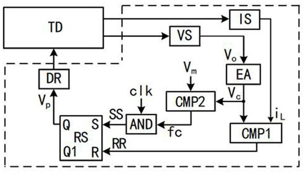
[0021] combined with figure 1 As shown, a voltage and current quasi-fixed frequency control device includes a voltage detection circuit VS, a current detection circuit IS, an error amplifier EA, a first comparator CMP1, a second comparator CMP2, an AND gate AND, a flip-flop RS and a driving circuit DR, the voltage detection circuit VS, the current detection circuit IS and the drive circuit DR are respectively connected to the voltage output terminal of the converter TD, the current output terminal of the converter, and the switch tube of the converter, and the voltage detection circuit VS is connected to the error amplifier EA; The detection circuit IS is connected to the input terminal of the first comparator CMP1; the output terminal of the error amplifier EA is connected to the input terminal of the first comparator CMP1 and the input terminal of the second comparator CMP2; the preset error signal reference value V m It is connected with the input end of the second comparat...

Embodiment 2

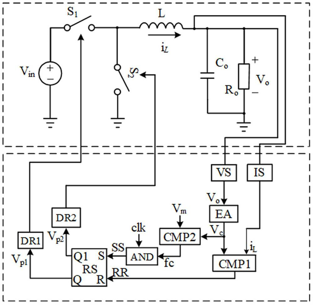
[0025] A quasi-fixed-frequency control method for voltage and current, realized based on the above-mentioned control device, the embodiment of the present invention replaces the converter TD in the above-mentioned embodiment with a synchronous rectification Buck converter, such as figure 2 As shown, the control method is:

[0026] At the beginning of any period, the converter TD output voltage V o and inductor current i L , output voltage V o with reference voltage V ref1 The voltage control signal V is generated through the error amplifier EA c ;Inductor current i L connected to one input terminal of the first comparator CMP1, and the voltage control signal V c After comparison, the signal RR is generated as the input signal of the R terminal of the flip-flop RS; the preset error signal reference value V m with voltage control signal V c Also connected to the input terminal of the second comparator CMP2, the preset error signal reference value V m with voltage contro...

Embodiment 3

[0035] Such as Figure 9 As shown, the embodiment of the present invention replaces the converter TD in the above embodiments with a Boost converter. In the figure, V in is the input voltage, L is the power inductor, S is the power switch tube, C o is the output capacitance, R o is the load resistance, VS is the output voltage detection circuit, IS is the inductor current detection circuit, V p1 It is the pulse control signal of the switch tube S.

[0036] The invention can also be used in various circuit topologies such as Buck-Boost converters, Flyback converters, and Forward converters, and is suitable for switching converters of various topological structures.


PUM


Abstract

The invention discloses a voltage and current quasi-fixed-frequency control device which comprises a voltage detection circuit, a current detection circuit, an error amplifier, a first comparator, a second comparator, an AND gate, a trigger and a driving circuit, and is characterized in that the voltage detection circuit is connected with the error amplifier; the current detection circuit is connected with the input end of the first comparator; the output end of the error amplifier is connected with the input ends of the first comparator and the second comparator; the preset error signal reference value is connected with the input end of the second comparator; the output end of the second comparator is connected with the clock signal and the input end of the AND gate; the AND gate and theoutput end of the first comparator are connected with the trigger; and the output end of the trigger is connected with the driving circuit. The invention further discloses a control method. The deviceand the method have the advantages of small output voltage ripple, high load transient response speed, small switching frequency change range, stability, strong anti-interference capability and the like; and the device and the method are suitable for switching converters of various topological structures.

Description

technical field [0001] The invention relates to the technical field of power electronics, specifically, a voltage and current quasi-fixed frequency control device and method. Background technique [0002] In industry, switching converters often use pulse width modulation or pulse frequency modulation technology to control the output power. Pulse width modulation technology controls the output voltage by adjusting the width of the control pulse. It is a constant frequency control method and has the advantage of simple feedback control loop design, but it has low light load efficiency, slow dynamic response speed, electromagnetic Disadvantages such as serious interference; pulse frequency modulation technology has been widely used in the industry due to its excellent performance such as fast input transient response speed and load transient response speed, high light load efficiency, and its control idea is: by changing the frequency of the control pulse to achieve control Th...

Claims


Application Information

Patent Timeline
IPC IPC(8): H02M3/156H02M1/08H02M1/088
CPCH02M1/08H02M1/088H02M3/156
Inventor 贺明智唐嵩峰林润泽周述晗刘雪山周群杨成王指香
Owner SICHUAN UNIV
Why Eureka
Try Eureka