Sepic converter with output current compensation branch

A technology of output current and converter, which is applied in the field of Sepic converter, which can solve the problems of performance impact, poor tolerance to pulsating current, and reduce the dynamic response speed of the circuit, so as to achieve the effect of improving efficiency and improving output voltage ripple

Pending Publication Date: 2019-08-16
ZHEJIANG COLLEGE OF ZHEJIANG UNIV OF TECHOLOGY
View PDF0 Cites 2 Cited by
  • Summary
  • Abstract
  • Description
  • Claims
  • Application Information

AI Technical Summary

Problems solved by technology

However, common aluminum electrolytic capacitors have poor tolerance to pulsating current, and their performance is seriously affected by temperature; common filters (such as: LC filters) will reduce the dynamic response speed of the circuit

Method used


Image

  • Sepic converter with output current compensation branch
  • Sepic converter with output current compensation branch
  • Sepic converter with output current compensation branch

Examples


Embodiment 1

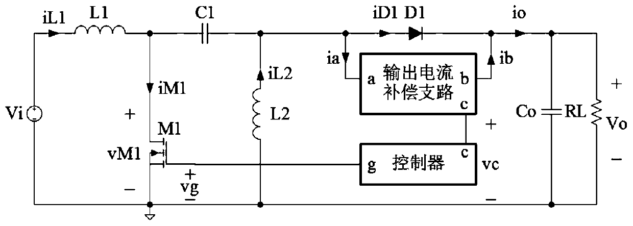
[0035] refer to figure 1 , a Sepic converter containing an output current compensation branch, including an inductance L1, an inductance L2, a capacitor C1, an N-channel MOS transistor M1, a diode D1, a capacitor Co, an output current compensation branch and a controller, the current compensation The branch circuit has port a, port b and port c, the controller has port g and port c, the positive end of the DC power supply Vi is connected to one end of the inductance L1, and the other end of the inductance L1 is simultaneously connected to the N-channel MOS transistor M1 The drain is connected to one end of the capacitor C1, and the other end of the capacitor C1 is connected to one end of the inductor L2, the port a of the output current compensation branch, and the anode of the diode D1, and the cathode of the diode D1 is connected to the port b of the output current compensation branch at the same time. , one end of the capacitor Co is connected to one end of the load RL, and...

Embodiment 2

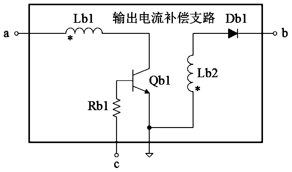
[0047] refer to figure 1 , image 3 and Image 6 , a Sepic converter with an output current compensation branch, the output current compensation branch includes an inductor Lb1, an inductor Lb2, an NPN BJT tube Qb1, a resistor Rb1 and a diode Db1, one end of the inductor Lb1 is connected to the output current compensation branch The other end of the inductor Lb1 is connected to the collector of the NPN BJT transistor Qb1, the emitter of the NPN BJT transistor Qb1 is connected to the source of the N-channel MOS transistor M1 and one end of the inductor Lb2, and the other end of the inductor Lb2 One end is connected to the anode of the diode Db1, the cathode of the diode Db1 is connected to the port b of the output current compensation branch, the base of the NPN type BJT tube Qb1 is connected to one end of the resistor Rb1, and the other end of the resistor Rb1 is connected to the output current compensation branch. The port c is connected, and there is a coupling relationshi...

Embodiment 3

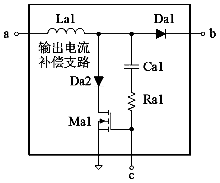
[0051] refer to figure 1 , Figure 4 and Image 6 , a Sepic converter with an output current compensation branch, the output current compensation branch includes an inductor Lc1, an inductor Lc2, an N-channel MOS transistor Mc1, a diode Dc1, and a diode Dc2, and one end of the inductor Lc1 is connected to the output current compensation branch The other end of the inductor Lc1 is connected to the anode of the diode Dc2 and one end of the inductor Lc2 at the same time, the other end of the inductor Lc2 is connected to the anode of the diode Dc1, and the cathode of the diode Dc1 is connected to the port b of the output current compensation branch. The cathode of the diode Dc2 is connected to the drain of the N-channel MOS transistor Mc1, the source of the N-channel MOS transistor Mc1 is connected to the source of the N-channel MOS transistor M1, and the gate of the N-channel MOS transistor Mc1 is connected to the output current compensation The port c of the branch is connecte...


PUM


Abstract

The invention provides a Sepic converter with an output current compensation branch. The converter comprises an inductor L1, an inductor L2, a capacitor C1, an N-channel MOS transistor M1, a diode D1,a capacitor Co, an output current compensation branch and a controller. In the output current compensation branch, when an N-channel MOS transistor M1 is turned off, a part of the current is shuntedfrom the inductor L1 and the inductor L2 through a port a thereof for energy storage, when the N-channel MOS transistor M1 is turned on, energy is released through a port b thereof, current is provided for the capacitor Co and a load RL, the controller adopts a soft switch controller, the switching state of the N-channel MOS transistor M1 is controlled through a port g thereof, and the working state of energy storage or release of the output current compensation branch is controlled through a port c thereof. The Sepic converter has the characteristics of low output voltage ripple and high efficiency.

Description

technical field [0001] The invention relates to a Sepic converter, especially a Sepic converter with an output current compensation branch, which not only has a small output voltage ripple, but also works in a soft switching state, and is suitable for applications with low output voltage ripple and high efficiency occasion. Background technique [0002] The output current of the traditional Sepic converter (referring to the current flowing through the freewheeling diode to the output terminal) is discontinuous, and this characteristic will cause its output voltage ripple to be large. To obtain a smaller output voltage ripple, the usual method is to increase the capacity of the output electrolytic capacitor or add a filter. However, common aluminum electrolytic capacitors have poor tolerance to pulsating currents, and their performance is seriously affected by temperature; common filters (such as: LC filters) will reduce the dynamic response speed of the circuit. [0003] T...

Claims


Application Information

Patent Timeline
Patent Type & Authority Applications(China)
IPC IPC(8): H02M3/156H02M1/14
CPCH02M1/143H02M3/156H02M1/0058H02M3/1557Y02B70/10
Inventor 陈怡张聚杜树旺
Owner ZHEJIANG COLLEGE OF ZHEJIANG UNIV OF TECHOLOGY
Why Eureka
Try Eureka