Buck-Boost converter with output current compensation branch
A technology of output current and converter, which is applied in the field of Buck-Boost converter, can solve problems such as poor pulsating current tolerance, performance impact, and reduced circuit dynamic response speed, etc., to achieve efficiency improvement, low output voltage ripple, and improved The effect of the output voltage ripple
- Summary
- Abstract
- Description
- Claims
- Application Information
AI Technical Summary
Problems solved by technology
Method used
Image
Examples
Embodiment 1
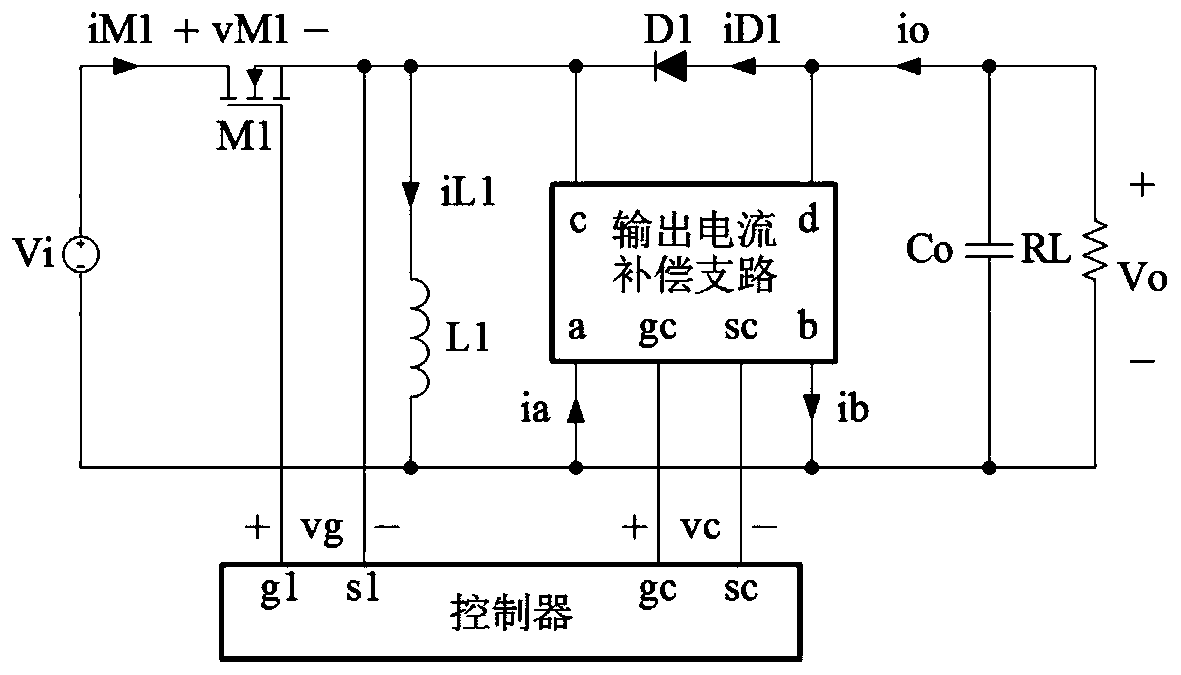
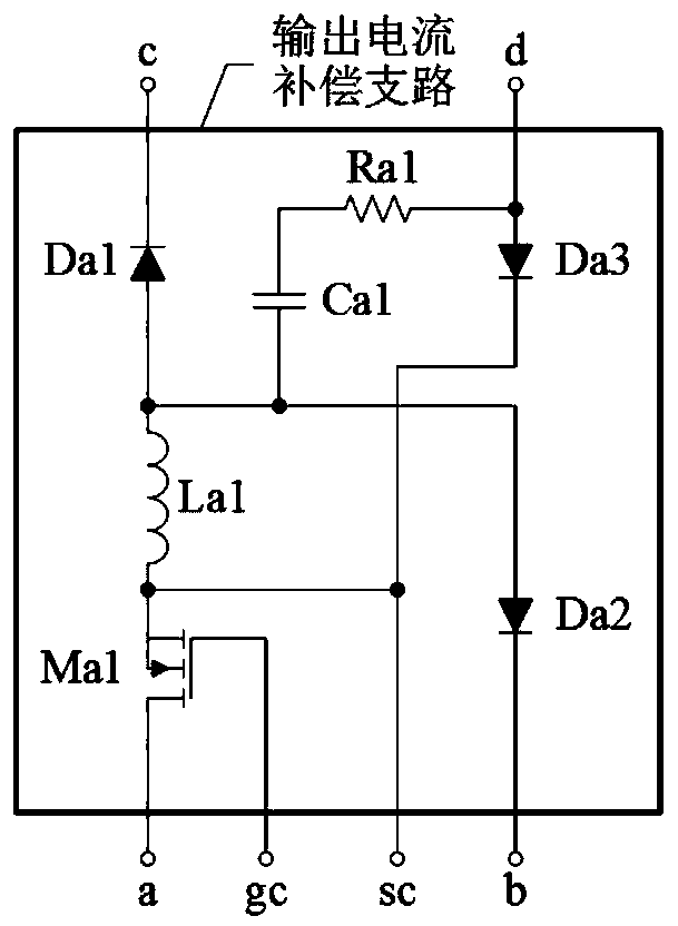
[0035] refer to figure 1 , a Buck-Boost converter with an output current compensation branch, including an N-channel MOS transistor M1, an inductor L1, a diode D1, a capacitor Co, an output current compensation branch and a controller, the current compensation branch has a port a, port b, port c, port d, port gc and port sc, the controller has port g1, port s1, port gc and port sc, the positive end of the DC power supply Vi and the drain of the N-channel MOS transistor M1 The source of the N-channel MOS transistor M1 is simultaneously connected to one end of the inductor L1, the port c of the output current compensation branch and the cathode of the diode D1, and the anode of the diode D1 is simultaneously connected to the port d of the output current compensation branch and the capacitor Co One end of the capacitor Co is connected to one end of the load RL, and the other end of the capacitor Co is connected to the other end of the load RL, the port b of the output current com...
Embodiment 2
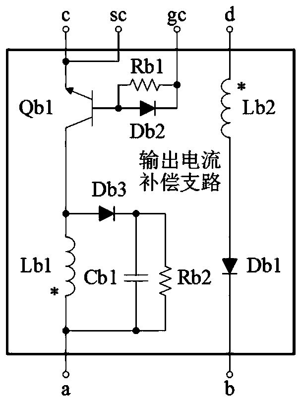
[0046] refer to figure 1 , image 3 and Figure 6 , a Buck-Boost converter with an output current compensation branch, the output current compensation branch includes an inductor Lb1, an inductor Lb2, an NPN BJT transistor Qb1, a diode Db1 and a resistor Rb1, and the emitter of the NPN BJT transistor Qb1 is simultaneously It is connected to port c and port sc of the output current compensation branch, the base of the NPN type BJT tube Qb1 is connected to one end of the resistor Rb1, and the other end of the resistor Rb1 is connected to the port gc of the output current compensation branch, and the NPN type BJT tube Qb1 The collector of the inductor Lb1 is connected to one end of the inductor Lb1, the other end of the inductor Lb1 is connected to the port a of the output current compensation branch, one end of the inductor Lb2 is connected to the port d of the output current compensation branch, and the other end of the inductor Lb2 is connected to the port of the diode Db1 T...
Embodiment 3
[0052] refer to figure 1 , Figure 4and Figure 6 , a Buck-Boost converter with an output current compensation branch, the output current compensation branch includes an inductor Lc1, an inductor Lc2, an N-channel MOS transistor Mc1, and a diode Dc1 to a diode Dc3, the cathode of the diode Dc1 is connected to the output current compensation The port c of the branch is connected, the anode of the diode Dc1 is connected with one end of the inductor Lc1 and the anode of the diode Dc2 at the same time, the cathode of the diode Dc2 is connected with the port b of the output current compensation branch, and the other end of the inductor Lc1 is connected with the output current compensation branch The port sc of the circuit, one end of the inductor Lc2, and the source of the N-channel MOS transistor Mc1 are connected, the drain of the N-channel MOS transistor Mc1 is connected to the port a of the output current compensation branch, and the gate of the N-channel MOS transistor Mc1 I...
PUM
 Abstract
Description
Claims
Application Information
 - R&D
- Intellectual Property
- Life Sciences
- Materials
- Tech Scout
- Unparalleled Data Quality
- Higher Quality Content
- 60% Fewer Hallucinations
Browse by: Latest US Patents, China's latest patents, Technical Efficacy Thesaurus, Application Domain, Technology Topic, Popular Technical Reports.
© 2025 PatSnap. All rights reserved.Legal|Privacy policy|Modern Slavery Act Transparency Statement|Sitemap|About US| Contact US: help@patsnap.com


