Boost converter comprising output current compensation branch
An output current, boost type technology, used in output power conversion devices, regulating electrical variables, high-efficiency power electronic conversion, etc., can solve performance impact, poor pulsating current tolerance, reduce circuit dynamic response speed and overall efficiency. and other problems to achieve the effect of improving efficiency and improving output voltage ripple
- Summary
- Abstract
- Description
- Claims
- Application Information
AI Technical Summary
Problems solved by technology
Method used
Image
Examples
Embodiment 1
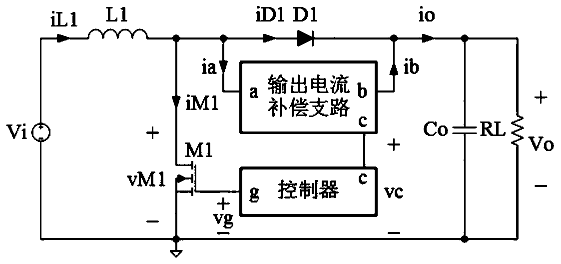
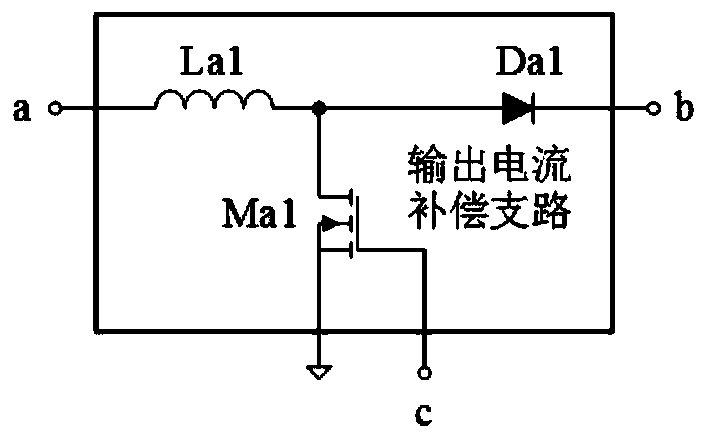
[0035] refer to figure 1, a boost converter with an output current compensation branch, including an inductor L1, an N-channel MOS transistor M1, a diode D1, a capacitor Co, an output current compensation branch and a controller, the current compensation branch has a port a, port b and port c, the controller has port g and port c, the positive end of the DC power supply Vi is connected to one end of the inductance L1, and the other end of the inductance L1 is simultaneously connected to the drain and output of the N-channel MOS transistor M1 The port a of the current compensation branch is connected to the anode of the diode D1, and the cathode of the diode D1 is connected to the port b of the output current compensation branch, one end of the capacitor Co and one end of the load RL at the same time, and the other end of the load RL is connected to the capacitor Co at the same time. The other end is connected to the source of the N-channel MOS transistor M1 and the negative te...
Embodiment 2
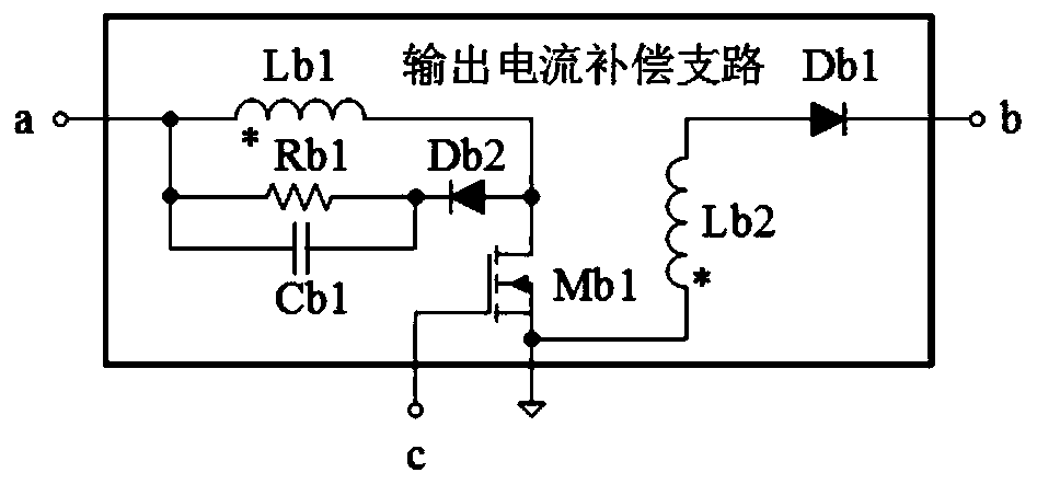
[0046] refer to figure 1 , image 3 with Image 6 , a boost converter with an output current compensation branch, the output current compensation branch includes an inductor Lb1, an inductor Lb2, an N-channel MOS transistor Mb1 and a diode Db1, one end of the inductor Lb1 is connected to the output current compensation branch port a, the other end of the inductor Lb1 is connected to the drain of the N-channel MOS transistor Mb1, the source of the N-channel MOS transistor Mb1 is simultaneously connected to the source of the N-channel MOS transistor M1 and one end of the inductor Lb2, and the inductor Lb2 The other end of the diode Db1 is connected to the anode of the diode Db1, the cathode of the diode Db1 is connected to the port b of the output current compensation branch, the gate of the N-channel MOS transistor Mb1 is connected to the port c of the output current compensation branch, the inductor Lb1 and the inductor Lb2 There is a coupling relationship, and one end of th...
Embodiment 3
[0051] refer to figure 1 , Figure 4 with Image 6 , a step-up converter with an output current compensation branch. The output current compensation branch includes an inductor Lc1, an inductor Lc2, an N-channel MOS transistor Mc1 and a diode Dc1. One end of the inductor Lc1 is connected to the output current compensation branch. The other end of the inductor Lc1 is connected to the drain of the N-channel MOS transistor Mc1 and one end of the inductor Lc2 at the same time, the other end of the inductor Lc2 is connected to the anode of the diode Dc1, and the cathode of the diode Dc1 is connected to the output current compensation branch. The port b is connected, the source of the N-channel MOS transistor Mc1 is connected to the source of the N-channel MOS transistor M1, the gate of the N-channel MOS transistor Mc1 is connected to the port c of the output current compensation branch, the inductor Lc1 and the inductor Lc2 There is a coupling relationship, and one end of the ind...
PUM
 Abstract
Description
Claims
Application Information
 - R&D
- Intellectual Property
- Life Sciences
- Materials
- Tech Scout
- Unparalleled Data Quality
- Higher Quality Content
- 60% Fewer Hallucinations
Browse by: Latest US Patents, China's latest patents, Technical Efficacy Thesaurus, Application Domain, Technology Topic, Popular Technical Reports.
© 2025 PatSnap. All rights reserved.Legal|Privacy policy|Modern Slavery Act Transparency Statement|Sitemap|About US| Contact US: help@patsnap.com


