Pseudo continuous conduction mode switch converter set follow current duty ratio control method and apparatus

A pseudo-continuous conduction, mode switching technology, applied in output power conversion devices, conversion equipment without intermediate conversion to AC, electrical components, etc., can solve problems such as the limitation of the load range of the converter, and achieve enhanced stability and dynamic response. capability, improve transient performance and efficiency, and ensure the effect of steady-state performance

Active Publication Date: 2015-12-23
SOUTHWEST JIAOTONG UNIV
View PDF3 Cites 5 Cited by
  • Summary
  • Abstract
  • Description
  • Claims
  • Application Information

AI Technical Summary

Problems solved by technology

The freewheeling control of the traditional PCCM switching converter adopts the constant-reference-current control (Constant-Reference-Current, CRC) method, which has a significant impact on the efficiency of the converter under light-load conditions. If the efficiency is low, the freewheeling current value needs to be reduced, but after reducing the freewheeling current value, the load range of the converter will be limited

Method used


Image

  • Pseudo continuous conduction mode switch converter set follow current duty ratio control method and apparatus
  • Pseudo continuous conduction mode switch converter set follow current duty ratio control method and apparatus
  • Pseudo continuous conduction mode switch converter set follow current duty ratio control method and apparatus

Examples


Embodiment 1

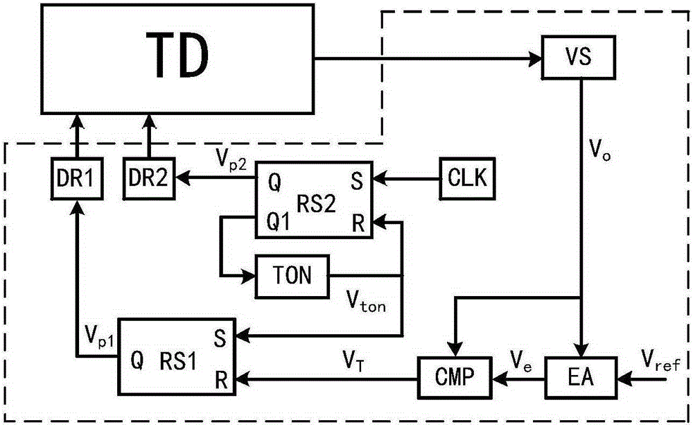
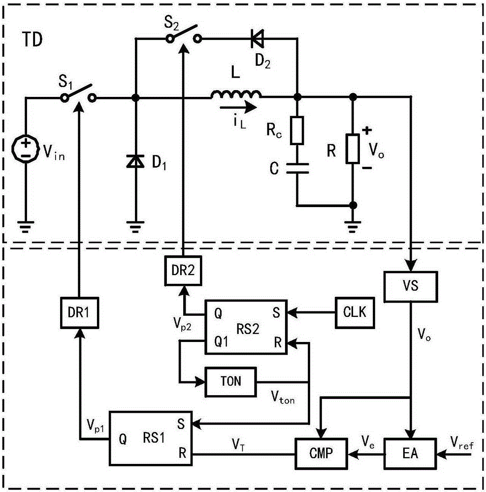
[0032] figure 1It is shown that a specific embodiment of the present invention is: a pseudo-continuous conduction mode switching converter constant current duty ratio control device, which is mainly composed of a voltage detection circuit VS, an error amplifier EA, a first trigger RS1, a second trigger RS2, a comparator CMP, a conduction timer TON, a clock signal CLK, a first driving circuit DR1 and a second driving circuit DR2. The voltage detection circuit VS is used to detect the output voltage V o value; the error amplifier EA is used to reference the voltage V ref and the output voltage V o The difference signal is amplified to generate the control voltage V e ;Comparator CMP is used to compare the output voltage V o and control voltage V e The size of the first flip-flop RS1 generates a reset signal; the first flip-flop RS1 is used to obtain the pulse signal V p1 , through the first drive circuit DR1 to control the turn-on and turn-off of the main switch tube; the ...

Embodiment 2

[0046] Such as Figure 8 As shown, this example is basically the same as the first example, except that the converter TD controlled in this example is a PCCM single-ended forward converter.

[0047] In addition to the switching converters in the above embodiments, the present invention can also be used in PCCM converter topologies such as PCCM half-bridge converters and PCCM full-bridge converters.


PUM


Abstract

The invention discloses a pseudo continuous conduction mode switch converter set follow current duty ratio control method and an apparatus. Through comparing a ripple voltage signal on an output capacitance equivalent series resistor to an error signal generated by an output voltage and a reference voltage which pass through an error amplifier, control to a main switch tube of a pseudo continuous conduction mode switch converter is completed and voltage stabilization of the output voltage is realized. Through carrying out set follow current duty ratio control on a follow current switch tube, dynamic follow current of an inductive current is realized. By using the method and the apparatus of the invention, the pseudo continuous conduction mode switch converter possesses the advantages that control is simple; stability is good; a load scope is wide; a light load output voltage ripple is small; input and a load transient response speed are fast; and full-load efficiency is high and so on.

Description

technical field [0001] The invention relates to a control method of a switching converter and a device thereof, in particular to a control method of a constant-flow duty ratio of a pseudo-continuous conduction mode switching converter and a device for realizing the constant-flow duty ratio control method. Background technique [0002] In recent years, with the development of power electronic device technology and power electronic converter technology, switching power supply has been widely used in industry, transportation, communication, etc. , IT and defense and other fields. [0003] Depending on the selection of circuit parameters, traditional switching converters will have two operating modes, namely: inductor current continuous conduction mode (continuousconductionmode, CCM) and inductor current discontinuous conduction mode (discontinuousconductionmode, DCM). Working in CCM mode, switching converters can deliver more energy to supply loads, and are widely used in medi...

Claims


Application Information

Patent Timeline
Patent Type & Authority Applications(China)
IPC IPC(8): H02M3/10H02M1/08H02M1/14
Inventor 周国华李振华冷敏瑞刘啸天
Owner SOUTHWEST JIAOTONG UNIV
Why Eureka
Try Eureka