
Locking mechanism, case and network equipment

A locking mechanism and locking state technology, applied in the direction of chassis/cabinet/drawer parts, electrical equipment shell/cabinet/drawer, data exchange details, etc., can solve elastic failure of shrapnel, unstable shrapnel structure, hook It can improve reliability and avoid locking failure by solving problems such as locking failure of side walls.

Inactive Publication Date: 2021-02-12
NEW H3C CLOUD TECH CO LTD
View PDF0 Cites 5 Cited by
  • Summary
  • Abstract
  • Description
  • Claims
  • Application Information

AI Technical Summary

Problems solved by technology

[0004] However, in the existing design, the release of the locking between the hook and the side wall of the bottom frame depends entirely on the elastic deformation of the shrapnel, and the structure of the shrapnel is unstable. Long-term use will cause the elasticity of the shrapnel to fail and cannot be restored to its original state. State, causing the lock between the hook and the side wall to fail, reducing the reliability of the lock between the upper cover and the bottom frame

Method used


Image

  • Locking mechanism, case and network equipment
  • Locking mechanism, case and network equipment
  • Locking mechanism, case and network equipment

Examples


Embodiment Construction

[0047]Here, exemplary embodiments will be described in detail, and examples thereof are shown in the accompanying drawings. When the following description refers to the accompanying drawings, unless otherwise indicated, the same numbers in different drawings represent the same or similar elements. The embodiments described in the following exemplary embodiments do not represent all the embodiments consistent with this specification.

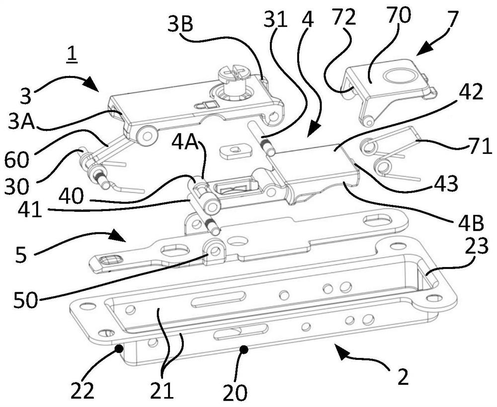
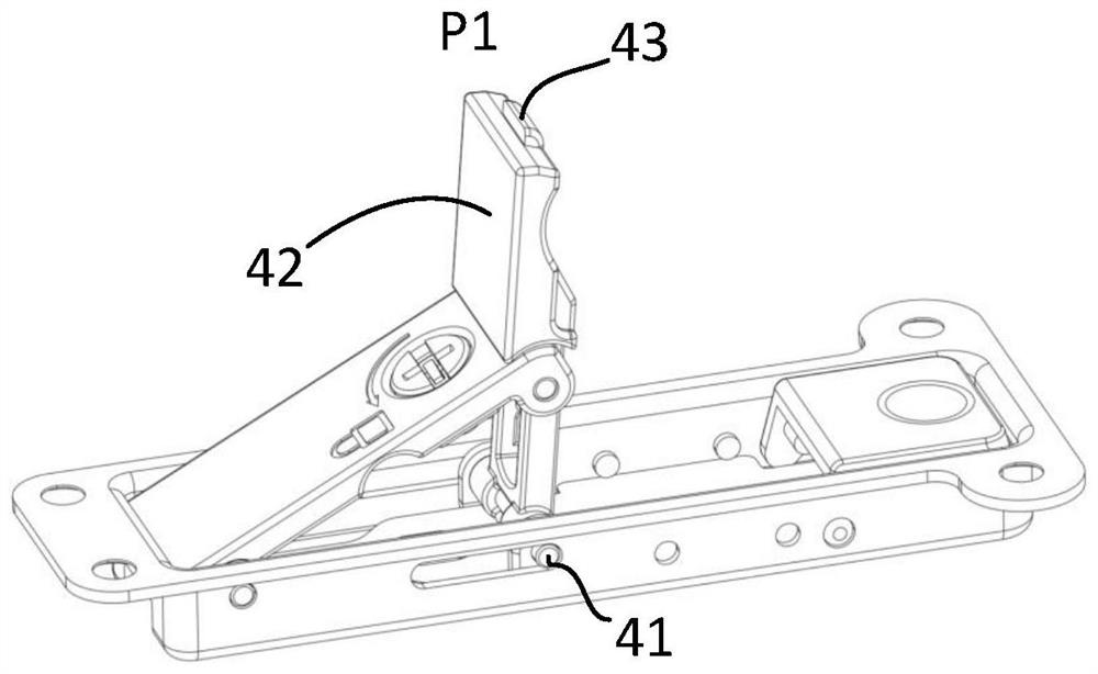
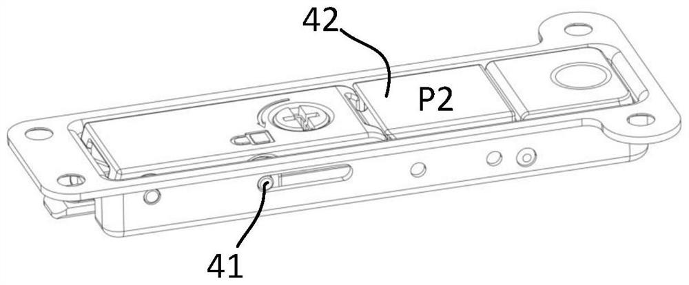
[0048]This application provides a locking mechanism 1, such asFigure 1-3As shown, the bottom case 2, the connecting piece 3, the operating piece 4 and the sliding piece 5 are included.

[0049]The bottom shell 2 includes a bottom wall 20, two side walls 21 and two end walls 22, 23. The bottom wall 20, the side walls 21 and the end walls 22, 23 enclose a cavity, a connecting piece 3, an operating piece 4 and The sliding plates 5 are respectively accommodated in the cavity.

[0050]The first end 3A of the connecting member 3 is rotatably connected to the end wall...


PUM


Abstract

The invention provides a locking mechanism, a case and network equipment, and relates to the technical field of communication equipment. The locking mechanism comprises a bottom shell, a connecting piece, an operating piece and a sliding sheet, wherein the side wall of the bottom shell is provided with a sliding groove; the connecting piece is rotationally connected to the first end of the bottomshell; the middle of the operating piece is rotationally connected to the connecting part; a sliding part, close to the first end of the bottom shell, of the operating piece is arranged in the slidinggroove; an operating part is arranged on one side, close to the second end of the bottom shell, of the operating piece; the sliding sheet is connected with the sliding part; when the operating part rotates to a first position far away from the bottom shell, the locking mechanism is in an unlocked state; and when the operating part rotates to a second position in the bottom shell, the locking mechanism is in a locked state.

Description

Technical field[0001]This specification relates to the technical field of communication equipment, and in particular to a locking mechanism, a chassis and a network device.Background technique[0002]With the development of the network, the demand for network equipment has gradually increased. In order to further improve the maintainability of network equipment, especially servers and storage devices, it is required to operate and maintain the equipment without shutting down. Therefore, it is necessary to implement cold plug, hot plug and other functions on the network equipment to ensure business Continuity.[0003]In terms of the hardware structure of the network equipment, it can be disassembled and assembled during operation. For example, the upper cover of the chassis of the network equipment needs to be separated from the bottom frame of the chassis, so that the internal structure can be cold-plugged and removed. Hot swap. In the existing case, an elastic piece is provided on the ...

Claims


Application Information

Patent Timeline
Patent Type & Authority Applications(China)
IPC IPC(8): H04L12/02H05K5/02
CPCH04L12/02H05K5/0208H05K5/0217H05K5/0221
Inventor 赵嘉文
Owner NEW H3C CLOUD TECH CO LTD
Learn More