Underwater polarization imaging method and device
A polarization imaging and polarization angle technology, which is applied in the field of underwater polarization imaging methods and devices, and can solve problems such as loss of target information in reconstructed images.
- Summary
- Abstract
- Description
- Claims
- Application Information
AI Technical Summary
Problems solved by technology
Method used
Image


Examples
Embodiment 1
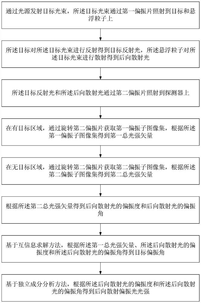
[0041] See figure 1 with figure 2 , figure 1 It is a flow chart of an underwater polarization imaging method provided by an embodiment of the present invention, figure 2 It is an underwater polarization imaging provided by an embodiment of the present invention, which is an angle diagram between backscattered light, target reflected light and total light intensity. An underwater polarization imaging method provided by an embodiment of the present invention includes:
[0042] Step 1. The light source 1 emits a target beam, and the target beam irradiates the target 6 and the suspended particles 5 through the first polarizer 2 .
[0043] Specifically, the underwater polarization imaging method of the present invention is mainly used to study the change of polarization information of light beams after being scattered by water bodies, so as to solve the problems of limiting imaging distance and reducing image contrast in underwater optical imaging by backscattered light. In t...
Embodiment 2
[0089] On the basis of Example 1, please refer to figure 1 with figure 2 , figure 1 It is a flowchart of an underwater polarization imaging method provided by an embodiment of the present invention, figure 2 It is an underwater polarization imaging provided by an embodiment of the present invention, which is an angle diagram between backscattered light, target reflected light and total light intensity.
[0090] Obtain the target polarization angle according to the first total light intensity vector, the polarization degree of the backscattered light and the polarization angle of the backscattered light, including:
[0091] Step 7.1. Obtain the light intensity of the reflected light and the light intensity of the backscattered light of the target through a plurality of different hypothetical target polarization degrees and hypothetical target polarization angles.
[0092]Specifically, the mutual information indicates the degree of correlation between two pieces of informat...
Embodiment 3
[0122] On the basis of Example 1, please refer to figure 1 with figure 2 , figure 1 It is a flowchart of an underwater polarization imaging method provided by an embodiment of the present invention, figure 2 It is an underwater polarization imaging provided by an embodiment of the present invention, which is an angle diagram between backscattered light, target reflected light and total light intensity.
[0123] According to the degree of polarization of the backscattered light and the polarization angle of the backscattered light, the light intensity of the backscattered polarized light is obtained.
[0124] Step 8.1. In the target area, obtain the corresponding light intensity I when the polarization azimuth angles are 0°, 45°, 90° and 135° by rotating the second polarizer 0 , I 45 , I 90 and I 135 .
[0125] Light intensity I 0 , I 45 , I 90 and I 135 The expression is:
[0126]
[0127] Step 8.2, according to the polarization angle and light intensity I of ...
PUM
 Abstract
Description
Claims
Application Information
 - R&D
- Intellectual Property
- Life Sciences
- Materials
- Tech Scout
- Unparalleled Data Quality
- Higher Quality Content
- 60% Fewer Hallucinations
Browse by: Latest US Patents, China's latest patents, Technical Efficacy Thesaurus, Application Domain, Technology Topic, Popular Technical Reports.
© 2025 PatSnap. All rights reserved.Legal|Privacy policy|Modern Slavery Act Transparency Statement|Sitemap|About US| Contact US: help@patsnap.com