Fire extinguisher shaking-up device for fire protection

A fire extinguisher and fire-fighting technology, which is applied in fire rescue and other fields, can solve the problems of low efficiency, unsatisfactory effect, and easy consumption of firefighters' physical strength, etc., and achieve the effects of increasing the force, improving the wind-shielding effect, and improving the shock effect

Active Publication Date: 2021-02-23
SHANGHAI TYKELONG VALVE CO LTD
View PDF15 Cites 0 Cited by
  • Summary
  • Abstract
  • Description
  • Claims
  • Application Information

AI Technical Summary

Problems solved by technology

Before using traditional fire extinguishers, most of the fire extinguishers use artificial shaking to distribute the internal materials evenly, so as to better carry out fire extinguishing operations. certain limitations

Method used


Image

  • Fire extinguisher shaking-up device for fire protection
  • Fire extinguisher shaking-up device for fire protection
  • Fire extinguisher shaking-up device for fire protection

Examples


Embodiment 1

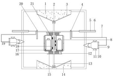
[0029] refer to Figure 1-4 , a fire extinguisher shaking equipment for fire fighting, comprising a lower concave block 14, the two sides of the lower concave block 14 are welded with a support frame, the top of the support frame is welded with the same upper triangular end block 1, and the upper triangular end block 1 and The opposite side of the lower concave block 14 is provided with parallel slide rails 3, and the opposite side of the lower concave block 14 and the upper triangular end block 1 is provided with a mounting column 13, and the two ends of the mounting column 13 are rotatably connected by bearings. There is a pulley 2 slidingly connected with the slide rail 3, the two ends of the mounting column 13 close to the central axis are connected to the turntable 15 through bearing rotation, and the opposite side of the turntable 15 is welded with a vibrating spring 16, and the opposite side of the vibrating spring 16 The same placement cylinder 17 is welded, and the ci...

Embodiment 2

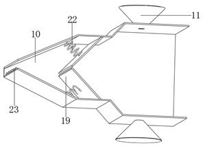
[0039] refer to figure 1 and Figure 5 , a fire extinguisher shaking equipment for fire fighting. Compared with Embodiment 1, this embodiment also includes two side springs 12 that are welded with staggered distribution on the opposite side of the two turntables 15 and the placement cylinder 17; The side springs 12 staggered between the tubes 17 can aggravate the imbalance in the horizontal direction of the tubes 17 during the up and down vibration of the tubes 17 and improve the vibration effect.

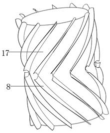
[0040] In the present invention, the inner arc side of the baffle 8 is welded with multiple ribs 26 equidistantly distributed, and the radians of the multiple ribs 26 and the baffle 8 are the same; the multiple ribs 26 arranged on the baffle 8 can improve its surface area, thereby effectively improving the windshielding effect of the baffle 8.

[0041] When the present invention is in use: the side springs 12 arranged in a staggered manner between the turntable 15 and the placeme...


PUM


Abstract

The invention belongs to the technical field of fire protection, and particularly relates to a fire extinguisher shaking-up device for fire protection. In order to solve the problems that before a traditional fire extinguisher for fire protection is used, a manual shaking mode is generally adopted to make internal substances uniformly distributed, but the effect is not satisfactory, the followingscheme is proposed. The fire extinguisher shaking-up device comprises a lower concave block, wherein supporting frames are welded to the two sides of the lower concave block, the same upper triangularend block is welded to the top ends of the supporting frames, parallel sliding rails are arranged on the opposite sides of the upper triangular end block and the lower concave block, and mounting columns are arranged on the opposite sides of the lower concave block and the upper triangular end block. Through arranged driving mechanisms, connecting arms and the mounting columns can be pushed to reciprocate along the sliding rails on the upper triangular end block and the lower concave block through connecting sliding blocks and push-pull boxes by utilizing the staggered operation of two hydraulic rods, so that the horizontal height position of a placement barrel is continuously changed; and under the action of vibration springs, the placement barrel vibrates.

Description

technical field [0001] The invention relates to the technical field of firefighting, in particular to a fire extinguisher shaking device for firefighting. Background technique [0002] Firefighting is to eliminate hidden dangers and prevent disasters (that is, the general term for preventing and solving the man-made, natural, and accidental disasters that people encounter in the process of life, work, and study). Of course, the narrow meaning means extinguishing fires in the early stages of people's understanding. Firefighting mainly includes rescue of personnel at the fire scene, rescue of important facilities and equipment, cultural relics, safety protection and rescue of important property, fire extinguishing, etc. The purpose is to reduce the degree of damage caused by the fire, reduce casualties and property losses. In wartime, it is under the unified command of the civil air defense headquarters at all levels, with professional firefighting forces as the backbone, mob...

Claims


Application Information

Patent Timeline
Patent Type & Authority Applications(China)
IPC IPC(8): A62C13/76
CPCA62C13/76
Inventor 张木兰
Owner SHANGHAI TYKELONG VALVE CO LTD
Why Eureka
Try Eureka