A long-distance optical fiber inspection system based on optical fiber random laser

A long-distance optical fiber and random laser technology, which is used in the testing of machine/structural components, testing optical fiber/optical waveguide equipment, optical instrument testing, etc. Achieve a wide range of applications, enhanced visibility, and simple operation

Active Publication Date: 2022-05-24
UNIV OF ELECTRONICS SCI & TECH OF CHINA +2
View PDF7 Cites 0 Cited by
  • Summary
  • Abstract
  • Description
  • Claims
  • Application Information

AI Technical Summary

Problems solved by technology

[0005] The invention discloses a long-distance optical fiber detection system based on optical fiber random laser, aiming to solve the problems of inaccurate positioning of long-distance breakpoints and difficult identification of optical fiber types

Method used


Image

  • A long-distance optical fiber inspection system based on optical fiber random laser
  • A long-distance optical fiber inspection system based on optical fiber random laser

Examples


Embodiment 1

[0018] The present invention will be further described below with reference to the accompanying drawings and specific embodiments.

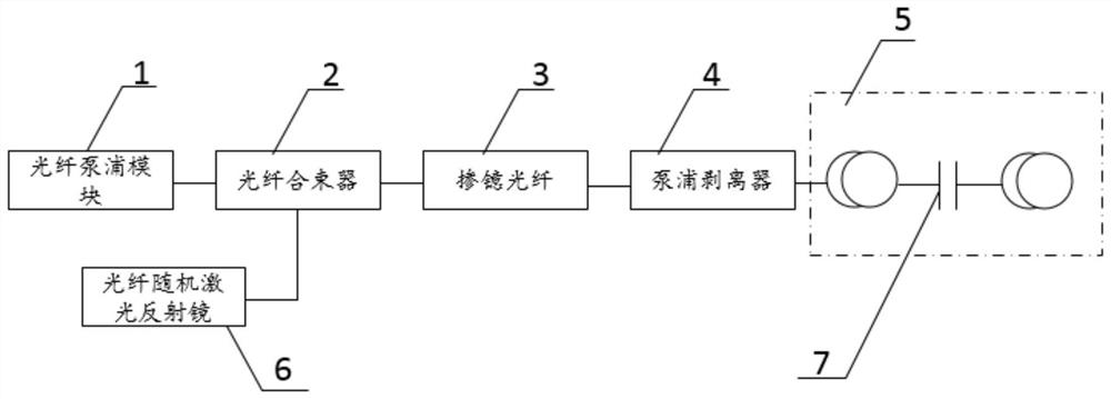
[0019] see figure 1 , a long-distance fiber detection system based on fiber random laser, its structure includes fiber pump module 1, fiber combiner 2, ytterbium-doped fiber 3, pump stripper 4, fiber to be tested 5 and fiber random laser reflector 6. The output end of the fiber pump module 1 is connected to the pump port of the fiber combiner 2, the signal end of the fiber combiner 2 is connected to the random fiber laser mirror 6, and the output end of the fiber combiner 2 is connected to the The input end of the ytterbium fiber 3 is connected, the output end of the ytterbium fiber 3 is connected with the input end of the pump stripper 4 for removing excess pump light, and the output end of the pump stripper 4 is connected with the fiber to be tested 5 . Possible breakpoints in the fiber to be tested7 such as figure 1 shown.

[0020] The pum...

Embodiment 2

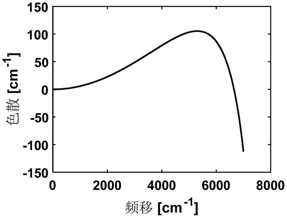
[0028] refer to figure 2 , figure 2 It shows the process of the present invention to produce visible light color selection in a demonstration fiber, wherein the two pump photons are both 1064 nm, the abscissa corresponds to the frequency shift of the new photons, and the ordinate is the comprehensive dispersion evaluation result. Under certain conditions, the two pump photons will excite the two new photons. When the sum of the material dispersion and the waveguide dispersion of the two newborn photons in the fiber under test is 0, stable excitation will be achieved and stable visible light will be generated. For G.652.D fiber, its zero dispersion frequency shift is 6650cm -1 , corresponding to the nascent visible light wavelength of 621 nm.

[0029] The specific four-wave mixing process is: 1064nm+1064nm=621nm+3700nm.

[0030] The 621nm light is orange light.

[0031] Therefore, if the system designed in the present invention detects that the optical fiber emits orange...


PUM


Abstract

This application discloses a long-distance optical fiber detection system based on optical fiber random laser, which relates to the field of optical fiber detection, and aims to simultaneously solve the problems of long-distance breakpoint location and fiber type identification, including fiber pump modules, fiber combiners, doped Ytterbium fiber, pump stripper, optical fiber to be tested and fiber random laser mirror; the output end of the fiber pump module is connected to the pump end of the fiber combiner, and the signal end of the fiber combiner is connected to the fiber random laser mirror , the output end of the fiber combiner is connected to the input end of the ytterbium-doped fiber, the output end of the ytterbium-doped fiber is connected to the input end of the pump stripper for removing excess pump light, and the output end of the pump stripper is connected to the input end of the pump stripper to be It is connected with the measuring optical fiber, the application system is easy to operate, the identification result of the optical fiber type is intuitive, and the breakpoint can realize long-distance positioning.

Description

technical field [0001] The invention relates to the field of optical fiber detection, in particular to a long-distance optical fiber detection system based on optical fiber random laser. Background technique [0002] Optical fibers made of quartz glass fibers have the advantages of anti-electromagnetic radiation interference, high temperature resistance, good electrical insulation, low loss, and intrinsic safety. They have been widely used in the fields of optical fiber communication and optical fiber sensing. Generally, the design life of ordinary fiber optic cable is 20 years. During the use process, it is inevitable that the fiber will be broken due to defects in fiber production, human damage, natural environment and other factors, which will cause interruption of communication and perception services. During fiber maintenance, it is often necessary to find breakpoints and re-splicing. Before optical fiber splicing, you need to confirm the type of optical fiber, which w...

Claims


Application Information

Patent Timeline
Patent Type & Authority Patents(China)
IPC IPC(8): G01M11/00
CPCG01M11/3127
Inventor 王子南林圣淘饶云江吴明埝栗鸣
Owner UNIV OF ELECTRONICS SCI & TECH OF CHINA
Why Eureka
Try Eureka