Pavement crack recognition method based on camera and line laser

A line laser and pavement crack technology, applied in the field of pavement crack identification, can solve problems such as interference, low identification accuracy, and dirt misidentified as cracks, etc., and achieve the effects of low investment cost, high intelligence, and intuitive identification results.

Active Publication Date: 2017-01-25
杭州华路中检检测技术有限公司
View PDF5 Cites 0 Cited by
  • Summary
  • Abstract
  • Description
  • Claims
  • Application Information

AI Technical Summary

Problems solved by technology

However, the camera detection method is easily disturbed by the garbage on the road surface, and it is easy to misidentify the dirt stuck on the road surface as cracks, resulting in low recognition accuracy.

Method used


Image

  • Pavement crack recognition method based on camera and line laser
  • Pavement crack recognition method based on camera and line laser
  • Pavement crack recognition method based on camera and line laser

Examples


Embodiment Construction

[0036] The present invention will be further explained below in conjunction with the drawings:

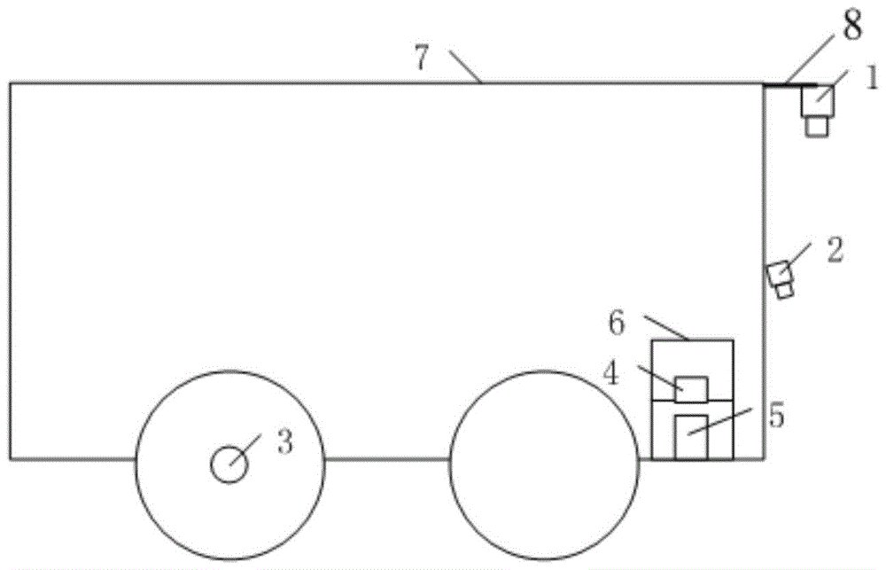
[0037] Reference figure 1 , Is a schematic diagram of the structure of the road crack identification device based on the camera and the line laser of the present invention. The road crack recognition device based on a camera and a line laser includes a vehicle 7, which is used to fix an area scan camera (high-speed area scan camera), a line laser, and the like. A flat panel 8 extending forward is installed at the center of the front of the vehicle 7. One end of the flat panel 8 is fixed at the center of the roof of the vehicle 7, and an area scan camera 1 is fixed under the other end of the flat panel 8 through bolts. The length of the plate 8 (the length in the forward direction of the vehicle) can be set as required. For example, the length of the plate 8 is between 20 cm and 80 cm. The lens of the area scan camera 1 faces the road surface vertically. The line laser 2 (laser used ...


PUM


Abstract

The invention belongs to the technical field of pavement crack recognition, and discloses a pavement crack recognition device based on a camera and a line laser, and a recognition method of the pavement crack recognition device. The pavement crack recognition device based on the camera and the line laser comprises a pulse counter, an industrial personal computer, a vehicle, a line laser fixedly mounted in the center of the head of the vehicle and a flat plate extending forward from the center of the head top of the vehicle; an area-array camera is fixed below one end of the flat plate; the angle between a laser head of the line laser and the horizontal plane is 40-80 degrees; a lens of the area-array camera vertically faces the ground; a rotary shaft of a rear wheel of the vehicle is coaxially sleeved with an incremental rotary encoder; the incremental rotary encoder is electrically connected with a counting end of the pulse counter; the output end of the pulse counter is electrically connected with a PCI card; the PCI card is inserted into a PCI slot of the industrial personal computer; the area-array camera is electrically connected with the PCI card through a Camera Link wire.

Description

Technical field [0001] The invention belongs to the technical field of road crack recognition, and particularly relates to a road crack recognition device and a recognition method based on a camera and a line laser. Background technique [0002] With the rapid development of highway construction in my country and the improvement of highway network construction, highway maintenance has also received more and more attention. After the road is built, cracks, bumps and other damage will appear on the road surface due to the repeated rolling of wheels and various natural factors such as ice, rain, and snow. Pavement cracks are one of the main forms of pavement diseases, which will affect the safety of driving and the service life of highways. Pavement cracks are an important indicator for evaluating highway quality. [0003] At present, the detection of road cracks mainly includes two methods: manual detection and camera detection. When manually detecting pavement cracks, inspectors n...

Claims


Application Information

Patent Timeline
Patent Type & Authority Patents(China)
IPC IPC(8): E01C23/01
Inventor 陈生客韩毅毛鹏宁兰
Owner 杭州华路中检检测技术有限公司
Why Eureka
Try Eureka