Self-walking mower

A self-propelled lawn mower technology, applied in the direction of harvesters, cutters, agricultural machinery and implements, etc., can solve problems such as being unfavorable to the precise positioning of self-propelled lawn mowers, interfering with the judgment of displacement, and easily slipping wheels.

Active Publication Date: 2021-03-05
NANJING CHERVON IND
View PDF5 Cites 0 Cited by
  • Summary
  • Abstract
  • Description
  • Claims
  • Application Information

AI Technical Summary

Problems solved by technology

The accuracy of GPS positioning is not high, and an error of 1-2 meters often occurs, which is not conducive to the precise positioning of the self-propelled lawn mower, making the self-propelled lawn mower work beyond the boundary, or miss cutting, and reduce the beauty of the lawn and reduced mowing efficiency
The path tracking and positioning of the self-propelled lawn mower refers to obtaining the linear velocity and the number of rotations of the driving wheel of the self-propelled lawn mower, so as to infer the cumulative displacement of the self-propelled lawn mower to estimate the position of the self-propelled lawn mower , and the lawn surface is slippery, the wheels are easy to slip, and the driving wheel rotation will be captured but the actual self-propelled lawn mower is not driving, thus reducing the accuracy of the position judgment of the self-propelled lawn mower
In the way of judging the displacement of the self-propelled lawn mower by acquiring the lawn image through the image sensor, the vegetation and the undulating ground will interfere with the judgment of the displacement of the self-propelled lawn mower by the image sensor, so that the accuracy of the self-propelled lawn mower cannot be realized. position

Method used


Image

  • Self-walking mower
  • Self-walking mower
  • Self-walking mower

Examples


Embodiment Construction

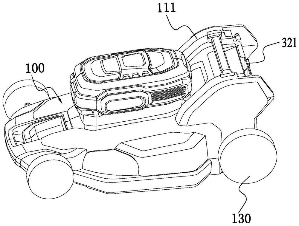
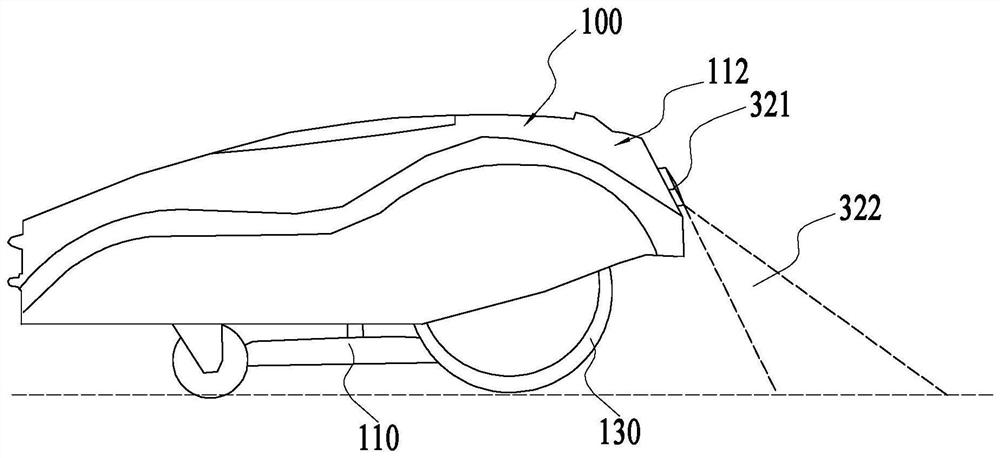
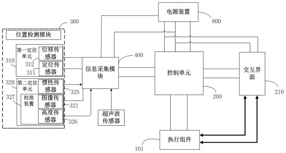
[0029] In one embodiment of the present invention, the present invention proposes a kind of self-propelled mower, with reference to Figure 1 to Figure 3b , the self-propelled lawn mower can be used to automatically mow the lawn and trim the lawn. The self-propelled mower at least includes a main body 100 and an executive assembly 101 connected to the main body. The executive assembly 101 includes a cutting blade 110 arranged on the main body 100 , and usually the cutting blade 110 is arranged under the main body 100 . The execution assembly 101 also includes an output motor 120 for driving the cutting blade 110 to rotate, and the cutting blade 110 is driven to rotate by the output motor 120 for cutting vegetation. The executive assembly 101 includes a drive wheel 130 and a drive motor 140 that provides driving force to the drive wheel 130 to rotate. The self-propelled mower includes a control unit 200 connected to the drive motor 140. The control unit 200 controls the drive m...


PUM


Abstract

The invention provides a self-walking mower. The self-walking mower comprises a shell, a cutting blade, drive wheels, a control unit which is connected with and controls a driving motor, and a position detection module which is used for detecting the position of the self-walking mower, wherein the position detection module comprises an image sensor which is used for sensing areas where the self-walking mower passes by and forming a plurality of position image information, and the image sensor forms first position image information and second position image information in a time sequence through induction, and the first position image information and second position image information have at least one common feature domain; the control unit obtains the relative displacement of the self-walking mower through analysis according to a movement track of the at least one common feature domain in time; and the position detection module further comprises a calibration device, and the calibration device is used for detecting posture information and / or position information of the self-walking mower so as to compensate for offset errors calculated according to the position image information ofthe image sensor. According to the self-walking mower, related parameters interfering the positioning of the image sensor can be detected to calibrate the positioning precision of the image sensor.

Description

technical field [0001] The invention relates to a garden electric tool, in particular to a self-propelled lawnmower. Background technique [0002] As an outdoor mowing tool, the self-propelled lawn mower does not require long-term operation by the user, and is favored by users for its intelligence and convenience. The self-propelled lawn mower's more autonomous control method requires its accurate judgment of its position, so that the self-propelled lawn mower can mow grass accurately in the preset mowing area, so the location of the self-propelled lawn mower Particularly important. The positioning method of the existing self-propelled lawn mower is usually through GPS positioning or path tracking positioning. The accuracy of GPS positioning is not high, and an error of 1-2 meters often occurs, which is not conducive to the precise positioning of the self-propelled lawn mower, making the self-propelled lawn mower work beyond the boundary, or miss cutting, and reduce the be...

Claims


Application Information

Patent Timeline
IPC IPC(8): A01D34/00A01D34/82G05D1/02
CPCA01D34/008A01D34/64G05D1/0246
Inventor 陈伟鹏梅庆枭杨德中
Owner NANJING CHERVON IND
Why Eureka
Try Eureka