Check patentability & draft patents in minutes with Patsnap Eureka AI!

Inductive angle sensor

An angle sensor and inductive technology, applied in the field of non-directional devices, can solve the problems of being susceptible to external magnetic field interference, uncertainty of angular displacement, unclear relationship between the phase and amplitude of induced current, etc.

Active Publication Date: 2021-03-05
INFINEON TECH AG
View PDF11 Cites 0 Cited by
  • Summary
  • Abstract
  • Description
  • Claims
  • Application Information

AI Technical Summary

Problems solved by technology

However, they may be susceptible to interference from external magnetic fields
Furthermore, they may only have limited resolution relative to their angular measurement range
Furthermore, the relationship between the phase and magnitude of the measured induced current may be ambiguous over the full 360° revolution
That is, certain pairs of values ​​(phase, magnitude) may occur more than once over a full 360° revolution, which makes the determination of the angular displacement ambiguous because it introduces uncertainty into the determined angular displacement

Method used


Image

  • Inductive angle sensor
  • Inductive angle sensor
  • Inductive angle sensor

Examples


Embodiment Construction

[0020] In the following description, equal or equivalent elements or elements having equal or equivalent functions are denoted by equal or equivalent reference numerals.

[0021] Method steps described by and with reference to block diagrams may also be performed in a different order than depicted and / or described. Furthermore, method steps relating to specific features of a device may be replaced by said features of said device, and vice versa.

[0022] As an introduction to the principles presented in this paper, a brief definition of the term "k-fold symmetry" should be given: If a shape can be rotated 360° × x / k (x is any integer) about an axis to make it appear the same, then the The shape may have k-fold symmetry.

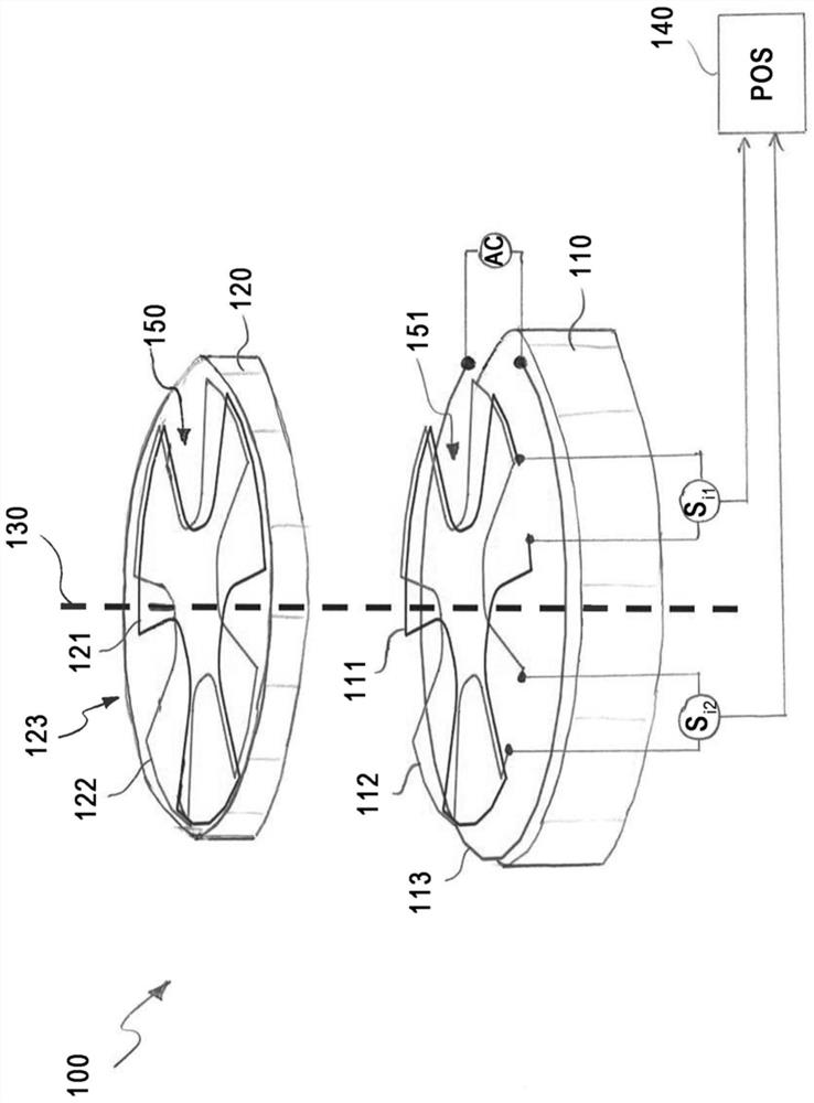
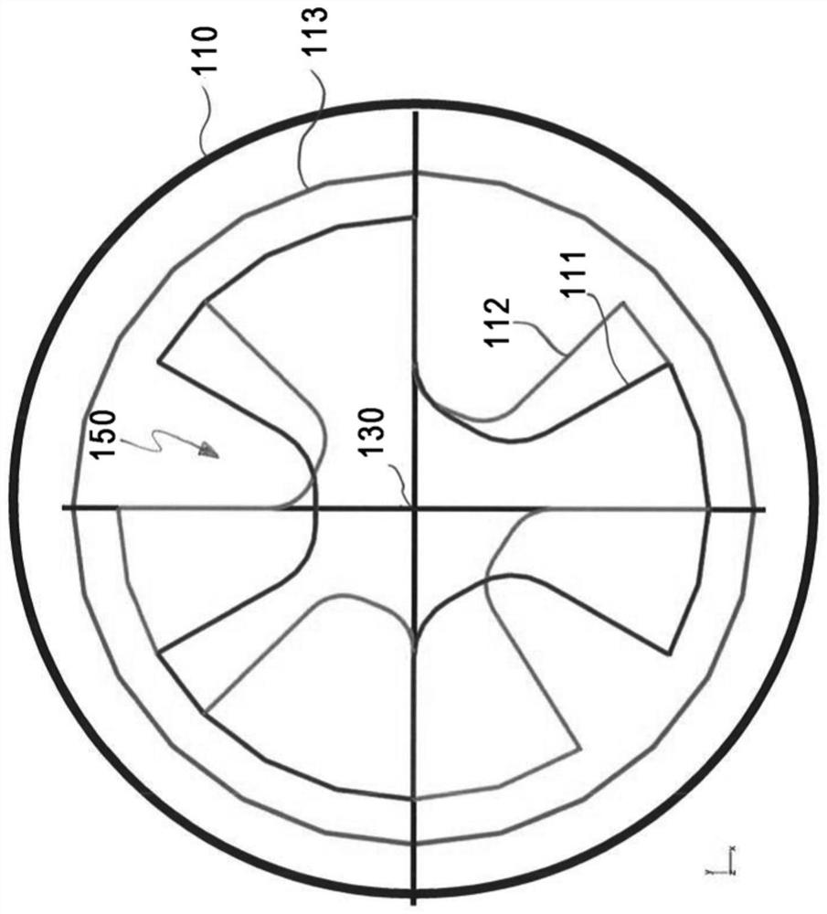
[0023] figure 1 An exemplary embodiment of an inductive angle sensor 100 according to the first aspect is shown. The inductive angle sensor 100 may include a stator 110 and a rotor 120 , and the stator 110 and the rotor 120 may rotate relative to each othe...


PUM


Abstract

The invention relates to an inductive angle sensor (100) for determining a rotational position of a rotor (120) relative to a stator (110). The inductive angle sensor (100) includes an exciter coil (113), at least one pickup coil arrangement (111) having an m-fold symmetry and at least one conductive target (121) having an m-fold symmetry. The exciter coil (113) may excite the conductive target (121) which, in turn, may induce an induced signal (Si1) in the pickup coil arrangement (111). A signal analysis device (140) may determine the rotational position of the rotor (130) based on the induced signal (Si1). At least one conductive target (121) is non-directional. The sensor may comprise a second pickup coil arrangement (112) having an n-fold symmetry and a second conductive target (122) having an n-fold symmetry. The second conductive target induces a second induced signal (Si2) in the second pickup coil arrangement (112). The signal analysis device (140) may determine the rotationalposition of the rotor (130) based on the two induced signals (Si1, Si2) according to a Vernier principle.

Description

technical field [0001] Embodiments of the present disclosure relate to an inductive angle sensor comprising a rotor and a stator, wherein the relative rotational displacement between the rotor and the stator can be determined using inductive principles. Some exemplary embodiments may relate to a particular geometric symmetry of one or more objects comprised by the rotor, and some exemplary embodiments may relate to an orientation-free device comprised by the stator and / or by the rotor, respectively. Background technique [0002] Inductive position sensors can generally be used to determine the relative displacement between two components that are movable relative to each other, wherein the determination of the relative displacement is based on the principle of electrical induction. For example, an inductive angle sensor can determine the relative linear or rotational displacement between two members. In the latter case, the first member may comprise a stator and the second ...

Claims


Application Information

Patent Timeline
IPC IPC(8): G01B7/30G01B7/004
CPCG01B7/30G01B7/004G01D5/2053G01D3/028G01D5/2291
Inventor U·奥塞勒克纳
Owner INFINEON TECH AG
Features
  • R&D
  • Intellectual Property
  • Life Sciences
  • Materials
  • Tech Scout
  • Unparalleled Data Quality
  • Higher Quality Content
  • 60% Fewer Hallucinations
Learn More