
Manifold

A technology of manifolds and conduits, used in instruments, measuring devices, mass flow measuring devices, etc., to solve problems such as unwanted audible noise, vibration, etc.

Pending Publication Date: 2021-03-09
MICRO MOTION INC
View PDF0 Cites 0 Cited by
  • Summary
  • Abstract
  • Description
  • Claims
  • Application Information

AI Technical Summary

Problems solved by technology

Vortex shedding can further cause vibration and unwanted audible noise

Method used


Image

  • Manifold
  • Manifold
  • Manifold

Examples


Embodiment Construction

[0037] The present application describes a manifold with reduced vortex shedding, a vibrating meter including the manifold, and methods of making both the manifold and the vibrating meter.

[0038] figure 1 Vibration meter 5 is depicted with manifold 150 according to an example. Such as figure 1 As shown, vibrating meter 5 includes meter assembly 10 and meter electronics 20 . The meter assembly 10 is responsive to the mass flow rate and density of the process material. Meter electronics 20 is connected to meter assembly 10 via wires 100 to provide density, mass flow rate and temperature information, among other information, via communication path 26 . Information and commands may also be received at meter electronics 20 via communication path 26 .

[0039] A Coriolis flowmeter structure is described, although this is not intended to be limiting. Those skilled in the art will readily appreciate that the present application may be practiced as a vibrating tube densitometer,...


PUM


Abstract

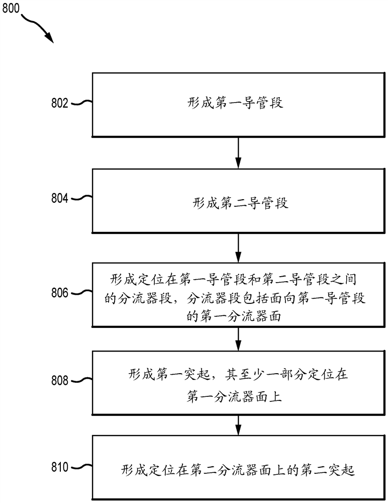
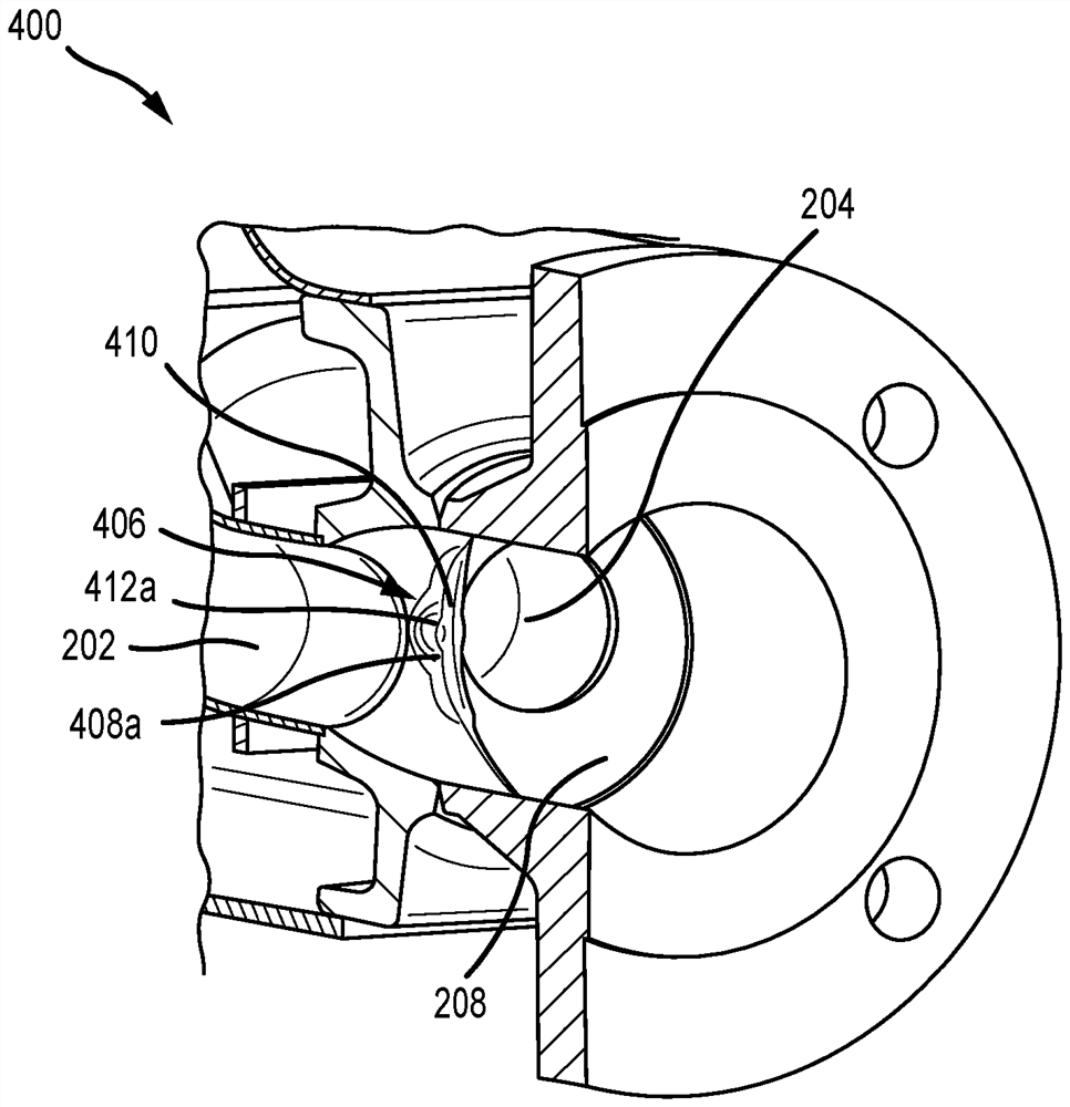
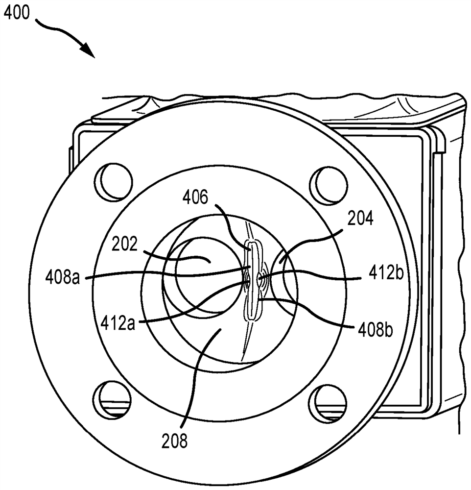
A manifold (400, 600, 700) with reduced vortex shedding, a vibratory meter (5) including the same, and a method of manufacturing both are described. The manifold (400, 600, 700) comprises a first conduit section (202), a second conduit section (204), a splitter section (406, 606, 706) positioned between the first conduit section (202) and the second conduit section (204), the splitter section (406, 606, 706) including a first splitter face (408a, 608a, 708) facing the first conduit section (202), and a first protrusion (412a, 612a, 712), at least a portion of which is positioned on the first splitter face (408a, 608a, 708).

Description

technical field [0001] The examples described below relate to manifolds and methods for making manifolds. More particularly, these examples relate to manifolds having diverters that include protrusions. Background technique [0002] Dual conduit Coriolis mass flow meters operate by sensing the motion of a pair of vibrating conduits, or flow tubes, that contain a flowing material. Properties associated with the material in the conduit, such as mass flow, density, etc., may be determined by processing measurement signals received from pickoffs or motion transducers associated with the conduit. [0003] Vibration meters can include assemblies with straight or curved conduits. As material begins to flow through the conduit, the Coriolis force causes each point along the conduit to have a different phase. For example, the phase at the inlet port of a flow meter lags the phase at the center driver location, while the phase at the outlet leads the phase at the center driver loca...

Claims


Application Information

Patent Timeline
Patent Type & Authority Applications(China)
IPC IPC(8): G01F1/84G01F1/684
CPCG01F1/6842G01F1/8409F15D1/06G01F1/8404
Inventor D·斯金克尔A·W·潘克拉茨J·D·福斯特
Owner MICRO MOTION INC
Learn More