A high-efficiency joint filling device for floor tiling for construction engineering

A construction engineering and ground technology, applied in the direction of buildings and building structures, can solve the problems of deviation of filling trajectory, reduce the efficiency of filling gaps, and low friction, so as to reduce the possibility of shaking, improve the degree of automation, and improve the squeeze. effect of stress

Active Publication Date: 2022-01-04
王保松
View PDF6 Cites 0 Cited by
  • Summary
  • Abstract
  • Description
  • Claims
  • Application Information

AI Technical Summary

Problems solved by technology

[0002] At present, in construction projects, in home decoration, in order to beautify the space between bricks and improve the comfort of the living environment, the gap between two adjacent bricks will be filled. Smooth floor tiles, but when filling, the friction of the general filling device is small when it contacts the floor tiles, it is easy to slip and shift, resulting in the deviation of the filling trajectory, and it is necessary to re-fill the joints, which greatly reduces the filling time. s efficiency

Method used


Image

  • A high-efficiency joint filling device for floor tiling for construction engineering
  • A high-efficiency joint filling device for floor tiling for construction engineering
  • A high-efficiency joint filling device for floor tiling for construction engineering

Examples


Embodiment 1

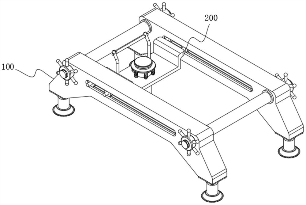
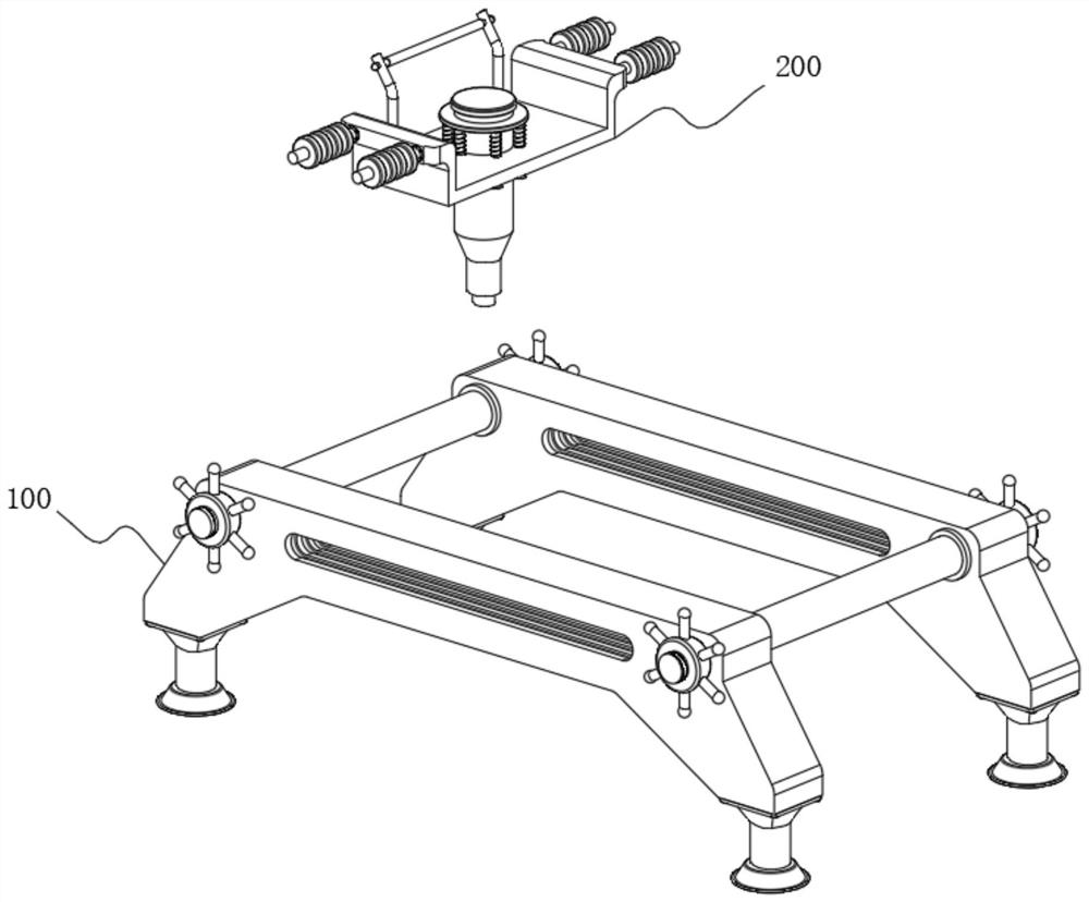
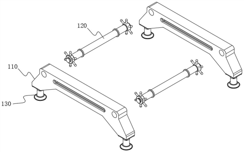
[0055] See Figure 1 - Figure 11 As shown, the present embodiment is an object of which provides a high-efficiency fill device for building engineering ground brick, including a restricted mechanism 100 and a fill mechanism 200 disposed inside the limit guiding mechanism 100, characterized in that it is: The bit guide 100 includes two guide frame 110, and there is a connection shaft 120 between the two guide frames 110, and the connecting shaft 120 is fixed to the guide frame 110, and the bottom of the guide frame 110 is symmetrically provided with a limiting device 130, a limit device. 130 includes a restricted suction cup 131, and the top of the limit suction cup 131 is provided with a column 132 for fixing with the guide frame 110.

[0056]In this embodiment, the limit suction cup 131 is first moved, and the guide frame 110 is first moved, and the limit suction cup 131 at the bottom of the guide frame 110 is placed on both sides of the gap on the top of the slit to be filled, an...


PUM


Abstract

The invention relates to the technical field of construction engineering, in particular to a high-efficiency joint filling device for ground tiles used in construction engineering. It includes a limit guide mechanism and a caulking mechanism arranged inside the limit guide mechanism. The limit guide mechanism includes two guide frames, and a connecting shaft is symmetrically arranged between the two guide frames. The guide frame is fixedly connected, and the bottom of the guide frame is symmetrically provided with a limit device, and the limit device includes a limit suction cup. By pressing the material storage tank, the sliding pipe moves upwards under the pressure of the brick surface, at this time, the feed hole is exposed in the cavity of the discharge tank, and then the raw materials in the discharge tank enter through the flow hole and the feed hole in sequence After entering the slide tube, it flows into the gap through the slide tube, and through the guidance of the guide groove and the limit of the limit suction cup, the moving route of the slide tube is more stable, so as to realize the precise filling of the gap and greatly improve the work efficiency.

Description

Technical field [0001] The present invention relates to the field of construction engineering, in particular, to a ground-fitting brick high-efficiency fill device for construction engineering. Background technique [0002] At present, in the construction project, in the home decoration, in order to beautify the brick and bricks, the comfort of the living environment will be filled with the gap between the two bricks, and the general home decoration is more Smooth floor tiles, but when filling, the general filling device is smaller when contacting the floor tile, which is easy to slip, resulting in a fill trapping, and re-filling, which greatly reduces the fill s efficiency. Inventive content [0003] It is an object of the present invention to provide a high-efficiency fill device for ground-fitting brick-friendly bricks to solve the problems raised in the above background. [0004] In order to achieve the above object, a high-efficiency filling device for building a building e...

Claims


Application Information

Patent Timeline
Patent Type & Authority Patents(China)
IPC IPC(8): E04F21/165
CPCE04F21/165
Inventor 葛义保
Owner 王保松
Why Eureka
Try Eureka