Efficient ground tiling joint filling device for constructional engineering

A construction engineering and ground technology, applied in the direction of construction and building structure, can solve the problems of deviation of filling trajectory, reduce the efficiency of filling gap, and low friction, so as to reduce the possibility of shaking, improve the degree of automation, and improve the extrusion. effect of stress

Active Publication Date: 2021-03-12
王保松
View PDF6 Cites 0 Cited by
  • Summary
  • Abstract
  • Description
  • Claims
  • Application Information

AI Technical Summary

Problems solved by technology

[0002] At present, in construction projects, in home decoration, in order to beautify the space between bricks and improve the comfort of the living environment, the gap between two adjacent bricks will be filled. Smooth floor tiles, but when filling, the friction of the general filling device is small when it contacts the floor tiles, it is easy to slip and shift, resulting in the deviation of the filling trajectory, and it is necessary to re-fill the joints, which greatly reduces the filling time. s efficiency

Method used


Image

  • Efficient ground tiling joint filling device for constructional engineering
  • Efficient ground tiling joint filling device for constructional engineering
  • Efficient ground tiling joint filling device for constructional engineering

Examples


Embodiment 1

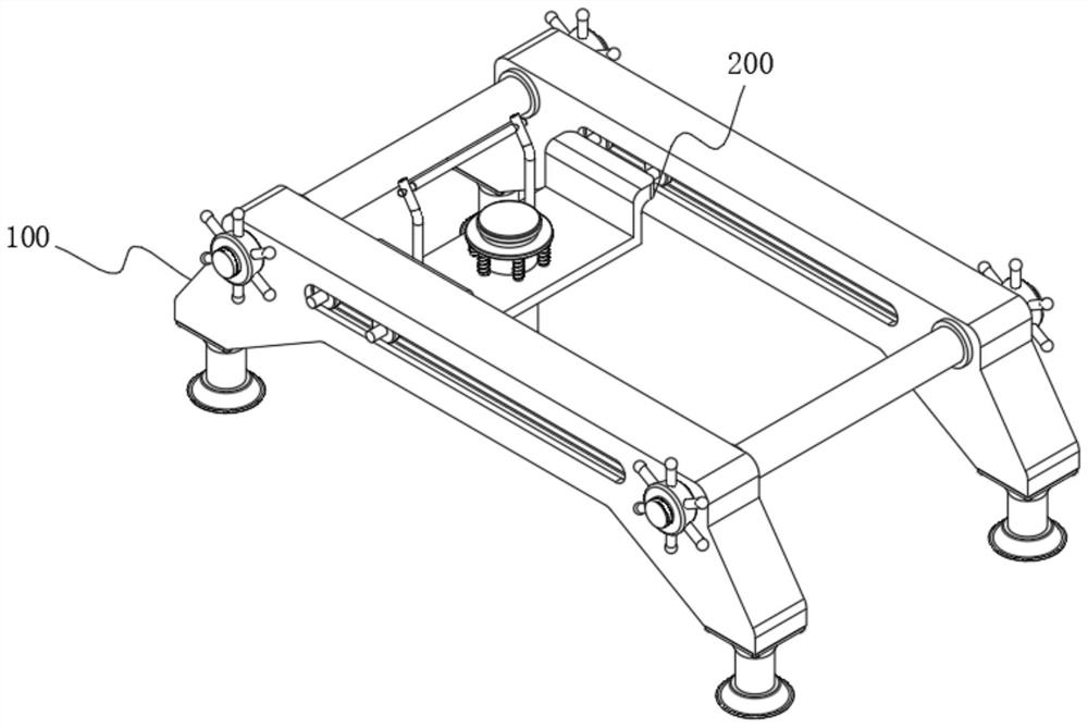
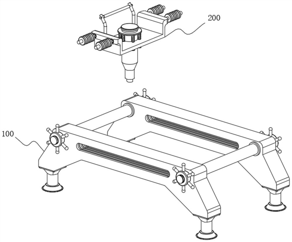
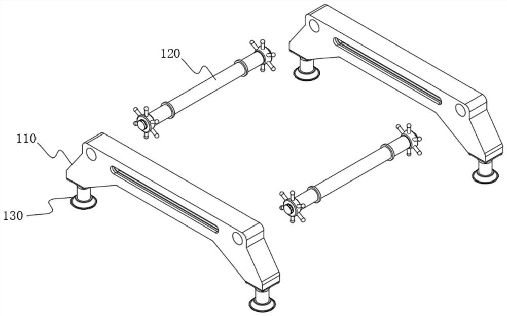
[0055] see Figure 1-Figure 11 As shown, the purpose of this embodiment is to provide a high-efficiency joint filling device for floor tiles for construction engineering, including a position limiting guide mechanism 100 and a joint filling mechanism 200 arranged inside the position limit guide mechanism 100, which is characterized in that: Position guide mechanism 100 comprises two guide frames 110, is provided with connecting shaft 120 symmetrically between two guide frames 110, and connecting shaft 120 is fixedly connected with guide frame 110, and the bottom of guide frame 110 is symmetrically provided with limit device 130, and limit device 130 includes a limit suction cup 131 , and the top of the limit suction cup 131 is provided with a column 132 for fixed connection with the guide frame 110 .

[0056]In this embodiment, when the limit suction cup 131 is in specific use, first move the guide frame 110, place the limit suction cup 131 at the bottom of the guide frame 110...


PUM


Abstract

The invention relates to the technical field of constructional engineering, and particularly relates to an efficient ground tiling joint filling device for constructional engineering. The efficient ground tiling joint filling device comprises a limiting guide mechanism and a joint filling mechanism arranged in the limiting guide mechanism, wherein the limiting guide mechanism comprises two guide frames; connecting shafts are symmetrically arranged between the two guide frames and fixedly connected with the guide frames; and limiting devices are symmetrically arranged at the bottoms of the guide frames and comprise limiting suction cups. A sliding pipe moves upwards under the pressure effect of a tile face by pressing a material storage tank, at the moment, a feeding hole is exposed in a cavity of a discharging tank, then raw materials in the discharging tank enter the sliding pipe through a circulation hole and the feeding hole in sequence and then flow into a joint through the slidingpipe, the moving route of the sliding pipe is more stable through guiding of a guide groove and limiting of the limiting suction cups, and therefore accurate joint filling of the joint is achieved, and the work efficiency is greatly improved.

Description

technical field [0001] The invention relates to the technical field of construction engineering, in particular to a high-efficiency joint filling device for ground tiles used in construction engineering. Background technique [0002] At present, in construction projects, in home decoration, in order to beautify the space between bricks and improve the comfort of the living environment, the gap between two adjacent bricks will be filled. Smooth floor tiles, but when filling, the friction of the general filling device is small when it contacts the floor tiles, it is easy to slip and shift, resulting in the deviation of the filling trajectory, and it is necessary to re-fill the joints, which greatly reduces the filling time. s efficiency. Contents of the invention [0003] The object of the present invention is to provide a high-efficiency joint-filling device for floor tiles used in construction engineering, so as to solve the problems raised in the above-mentioned backgrou...

Claims


Application Information

Patent Timeline
IPC IPC(8): E04F21/165
CPCE04F21/165
Inventor 葛义保
Owner 王保松
Why Eureka
Try Eureka